The multimeter is every electronics person’s basic measuring instrument: it measures a voltage, a current, a resistance, and tests the continuity of a connection. It gives a single value — a number, not a waveform: to watch a fast-changing signal, the oscilloscope is the tool. Sturdy and present on every bench, it answers the vast majority of diagnostic questions: “is there 5 V here?”, “is this track broken?”, “what is the value of this resistor?“. This page is a tool tutorial of the measuring instruments hub.
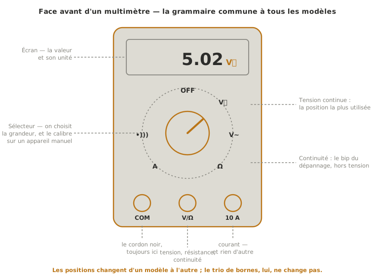
What is it for?
The common functions of a multimeter:
- DC voltage (V⎓ / DC) — checking a power supply (5 V, 3.3 V, battery voltage), reading a logic level;
- AC voltage (V∼ / AC) — measuring an alternating signal (RMS value) — rare in a project that lives on DC (mains 230 V stays out of bounds, cf. the hub, Voltage limits);
- resistance (Ω) — reading the value of a resistor, checking a resistive sensor (thermistor, photoresistor);
- continuity — a beep when the resistance is near zero: testing in seconds whether a track, a solder joint or a cable is properly connected;
- current (A) — measuring the current drawn by a build (in series, see below);
- often a diode test too, and sometimes capacitance or frequency.
For signals that change over time (PWM, serial frame, contact bounce), the multimeter is not enough. It displays an average or an unstable value: switch to the oscilloscope.
Measuring step by step
- Choose the function and the range with the selector: type of quantity (V⎓, V∼, Ω, A) and, on a manual meter, the appropriate range (start wide). Auto-range meters pick the range on their own.
- Plug the leads into the right terminals. The black lead always goes into COM. The red one goes into the V/Ω terminal to measure voltage, resistance and continuity — or into the current terminal (often “10 A” or “mA”) only to measure a current. This is the most error-prone point (see Pitfalls).
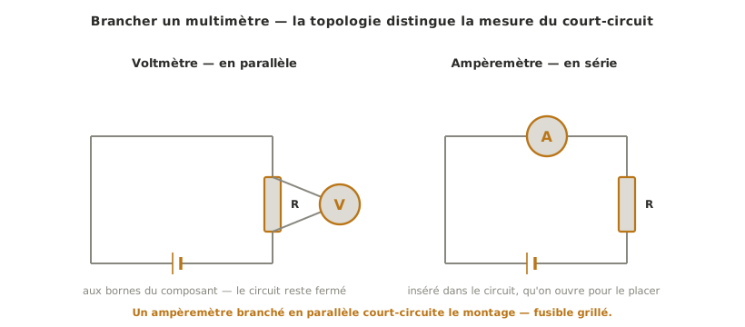
- Connect to the circuit according to the quantity:
- voltage → probes in parallel across the two points whose potential difference you want (the circuit stays powered);
- resistance / continuity → component with power off, ideally isolated from the rest of the circuit;
- current → in series, opening the circuit to insert the multimeter.
- Read the value and its unit, taking the range into account — and without over-reading the last digit: resolution is not accuracy.
Measuring a current without breaking the circuit
The field reflex: measure the voltage across a known resistor of the circuit, then divide — I = V / R. No circuit to open, no fuse at stake. It is the principle of the crossed Sense pins in the L298N datasheet.
Tip
Continuity mode is troubleshooting’s best friend. Before suspecting a component, check with the beep that every link is properly made: a broken cable, a cold solder joint or a cracked track is found in seconds, with the build switched off.
Example — Checking a board’s power supply
A microcontroller board does not start. Before anything else, check “is the power getting there, and at the right voltage?“.
- Supply — selector on V⎓, COM on the board’s ground (GND), red probe on the 5 V pin: expect ≈ 5 V. A very low value (3 V, 0 V) points to an insufficient supply, a charge-only USB cable, or a short circuit dragging the voltage down.
- Drop across an LED — probes across a lit LED: you read its forward voltage (≈ 2 V for a red one, ≈ 3 V for a blue one). This confirms it is properly polarised and powered.
- Continuity of a track — build switched off, continuity mode, one probe at each end of a suspect link: a beep confirms it passes, silence reveals the break.
In three simple measurements, you have narrowed the problem down to the supply, a component or a connection — without desoldering anything blindly.
Pitfalls
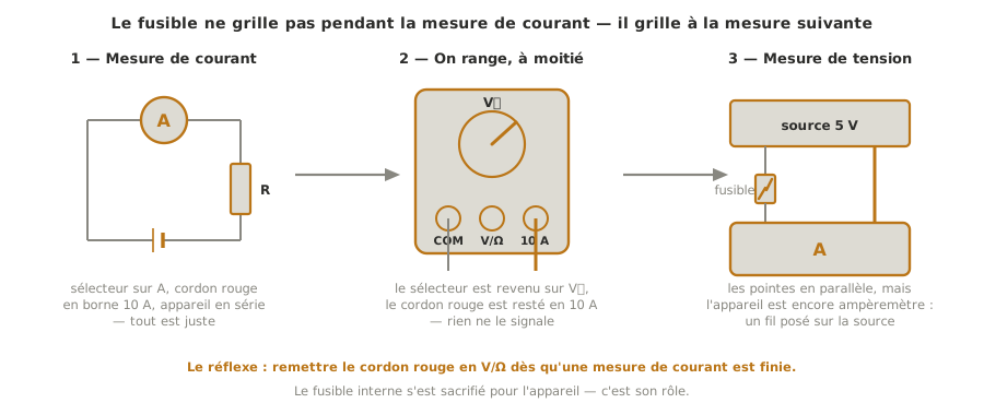
Ammeter left in current position, reconnected in parallel. The classic mistake: after a current measurement, you forget to put the red lead back into the V/Ω terminal and the selector back on voltage. Next time, you put the probes in parallel “to measure a voltage”, but the meter is still an ammeter: short circuit, blown fuse. The internal fuse is precisely a protection device: it sacrificed itself for the meter. Reflex: return to voltage measurement as soon as a current measurement is done.
Measuring a resistance under power. The ohmmeter function injects its own current: applied to a powered circuit, it reads garbage and can damage the meter. A resistance is measured with power off.
Reading the wrong range. On a manual meter, a range too small saturates (“1” or “OL” on the display), a range too large loses accuracy. Set the range, or take an auto-range meter.
Mixing up DC and AC. Measuring DC on the AC range (or the reverse) gives a wrong value. Check the ⎓ / ∼ position of the selector.
Forgetting the loading effect. On a very high-impedance node, the small current drawn by the voltmeter can pull the read voltage down. Rare in a project, but worth knowing (see the hub, Measuring is not neutral).
See also
- Measuring instruments — the hub: method and choice of instrument
- Oscilloscope — when the value is not enough and you need to see the shape of the signal
- Logic levels — the thresholds you check with the multimeter (prerequisite)
- Reading a datasheet — the expected value to compare the measurement with
- GPIO — checking with the multimeter the real state of a pin (HIGH / LOW)