Designing a power supply means giving every part of a system the voltage and the current it needs, cleanly and safely: choosing a source, regulating it to the right voltage, absorbing the peaks in consumption, organising the ground returns and protecting everything against wiring mistakes. It is the engineering of the supply / distribute block of the energy chain, the most underrated stage of a project, ignored while everything works and blamed unfairly as soon as some other fault turns up.
What is it for?
As long as a build sits on the bench, powered over USB, the question does not arise. It shows up as soon as you add power — a motor, a relay, a radio module, an LED strip: the current climbs, peaks appear, and the logic supply starts to move about. Thinking the power supply through before you get there lets you:
- size the source on the real consumption, peaks included, rather than on the average current;
- keep the voltage steady when an actuator starts, so that the microcontroller does not reset;
- keep the power noise away from the signal, by separating what carries energy from what carries information;
- make faults non-destructive: a short circuit or a reversed polarity should cut out, not burn out.
This work belongs to system design (the concept phase, then sizing in the technical design file). Putting it to work on a given board, for instance powering an Arduino board, applies these principles to specific hardware.
Choosing the source
Everything starts from a source, and choosing it comes before regulation: the source is what fixes what there will be to regulate. Four families cover most projects:
- USB (5 V) — the bench source: free, safe, but limited in current (0.5 A from an ordinary computer port, up to about 3 A from a recent charger) and unsuitable as soon as motors are involved;
- batteries and cells — mobility, at the price of a voltage that slides as they discharge (a Li-ion cell drops from 4.2 to 3.0 V): regulation becomes compulsory, and lithium calls for a dedicated protection and charging circuit;
- the mains adapter (typically 9 to 12 V) — stationary power, simple and plentiful, to be sized on the consumption peak;
- the bench power supply — the source for the testing stages: adjustable voltage and current limit (see Constant voltage or constant current below), the one that protects a new build.
The choice comes down to four criteria: the voltage (compatible with the regulation stage downstream), the peak current available (never the average current), the battery life if the system is mobile, and how safe it is to work with. The concrete figures for a given board — connectors, permitted ranges, currents available per pin — are found on that board’s page, for instance powering an Arduino board.
Regulating the voltage
A raw source (a battery discharging from 8.4 to 6 V, mains rectified to 9-12 V) does not directly give the steady 5 V or 3.3 V that the logic expects. A regulator brings a varying input down to a fixed output. There are two families, and two trade-offs.
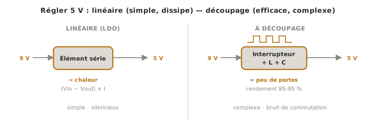
The linear regulator (an LDO, low-dropout) is simple, quiet and cheap: it behaves like a controlled resistor that soaks up the difference between input and output. The downside is mechanical: everything it does not send to the output leaves as heat, amounting to (Vin − Vout) × I. Producing 5 V from 9 V at 0.5 A dissipates (9 − 5) × 0.5 = 2 W, enough to burn your fingers without a heatsink. Keep it for small voltage differences and small currents, where its electrical cleanliness is what matters.
The switching regulator chops the energy into packets through an inductor: it dissipates almost nothing and reaches efficiencies of 85 to 95%, even across a large voltage difference. The price is complexity — more components, a carefully drawn board — and a switching noise that sometimes has to be filtered out. It is the default choice as soon as the current or the voltage difference gets large, and on battery, where every watt lost shortens the running time.
The detail of the topologies (buck, boost, their equations) belongs to the power electronics course. What gets decided at project level is which one to choose and how to size it.
Tip
Tried and tested parts — linear: 7805 (5 V, the classic), AMS1117 (compact, 5 V or 3.3 V), MCP1700 (very low quiescent LDO); switching: LM2596 or MP1584 buck modules, MT3608 boost. Stable, widely available families: start from them, check availability and read the datasheet before buying.
Decoupling
A regulator reacts quickly, but not instantly. When a component draws a brief current peak — a radio module transmitting, a motor starting, a logic output switching —, the local voltage collapses for as long as the regulation takes to catch up. A decoupling capacitor placed as close as possible to the component acts as a small reservoir: it supplies the peak locally, then recharges. (→ concept page decoupling)
You combine two types per stage: a bulk capacitor (a few tens to a few hundred µF) that takes the large variations, and a ceramic capacitor (typically 100 nF) right against the supply pin, which answers the fastest variations. The golden rule is three words: as close as possible. Decoupling ten centimetres away from the component, at the end of a long track, is next to useless. The inductance of the track cancels its effect.
Missing decoupling is what explains a good share of “unexplained” erratic behaviour: a sensor giving nonsense readings while a motor runs, a microcontroller crashing now and then. The peak is too brief to show up on a multimeter. It is flushed out with an oscilloscope.
Routing the grounds
Ground (0 V) is not a neutral wire: it is the return path for every current. A wire has resistance, however small, and any current flowing through it creates a voltage drop across it. If a motor’s return and a sensor’s reference share the same length of wire, the motor current shifts the sensor’s reference: the measured signal is wrong, without a single component being at fault.
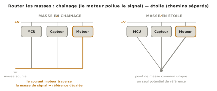
Hence the distinction between the power ground (returns from the actuators, heavy currents, sometimes noisy) and the signal ground (returns from the logic and the sensors, small currents to be protected). The aim is that they do not share their return paths, while remaining one and the same reference potential. The basic technique is the star ground: each return goes to a single common point rather than being chained onto the others. Daisy-chained grounds do the opposite: they route the heavy currents through shared segments and inject their noise into them.
The star ground is the technique for wired builds and for the breadboard. On a printed circuit board it becomes a ground plane: a whole layer given over to 0 V, which offers every return a short, low-impedance path. That is the reflex to acquire as soon as you start designing the board.
When you have two separate supplies — one for the logic, one for the motors —, the same rule calls for a common ground: with no shared reference, the logic signals exchanged between the two worlds mean nothing. It is the classic beginner’s mistake, powering the motors “separately” and forgetting to tie the grounds together.
Constant voltage or constant current
Most supplies hold a constant voltage (CV): they put out 5 V and let the load draw whatever current it wants, up to a limit. That is the mode logic expects. But some applications ask for the opposite — imposing a constant current (CC) and letting the voltage settle where it will: powering a power LED (where it is the current, not the voltage, that sets the brightness and the lifetime), or charging a battery.
A bench power supply makes this behaviour visible: you set a voltage and a current limit on it. As long as the load draws little, the instrument holds the voltage (CV mode). If the load asks for more than the limit — or in the event of a short circuit —, it switches to CC mode: it caps the current and lets the voltage fall. Setting that limit before a first run turns a potentially destructive short circuit into a harmless fallback: it is the reflex to acquire for testing a new build.
Protecting
A well-designed supply makes the common faults non-destructive. Three protections cover most projects. (→ concept page electronic protections)
Against the short circuit, a current limit: a fuse, which cuts out for good beyond a threshold, or an electronic foldback that caps the current (like CC mode). The threshold is set a little above the normal expected peak, never below, or it will trip for no good reason.
Against reversed polarity — plugging + and − the wrong way round, a classic mistake on an unkeyed connector —, a diode in series (simple, but it drops about 0.7 V and heats up) or, better, a MOSFET used as protection (negligible drop). Without one, a reversal can destroy the powered components instantly.
Against overvoltages (the spike when an inductive load is switched off, an electrostatic discharge, a mains transient), a TVS diode or a Zener diode clamps the peak before it reaches sensitive circuits. This is particularly useful near a relay or a motor, whose switch-off sends a spike back.
The general rule fits in one sentence: assume you will get it wrong when plugging in and wiring up, and arrange for the mistake to cost a fuse rather than a board.
Example — The 3-axis arm
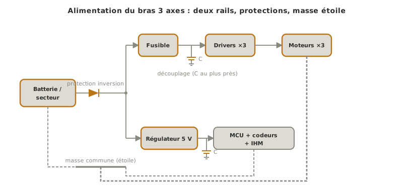
On the running example arm, the supply / distribute block of the energy chain takes shape as two rails from a single source. At the input, reverse-polarity protection guards the whole system against being plugged in backwards. The source then splits:
- a power rail, protected by a fuse sized on the peak of the three motors, feeds the drivers and then the motors;
- a 5 V regulator feeds the logic: the microcontroller, the encoders and the HMI.
Each rail carries its decoupling as close as possible: a bulk capacitor across the drivers, where the motors’ current demands are abrupt, a ceramic at the microcontroller’s supply pin. Finally, the returns from both rails meet at a common star ground near the source: the motor current never crosses the encoders’ reference, whose measured position would otherwise be spoiled by noise at every movement. It is that clean loop — command going down, measurement coming back up unpolluted — that lets the arm know where it is.
Pitfalls
Sizing on the average current. A supply is chosen on the consumption peak (motor start-up, radio transmission), not on the average. A margin of around 1.5× on the peak avoids voltage dips at full load.
Asking a linear regulator for a large drop. An LDO bringing 12 V down to 5 V at a few hundred mA heats up fast: (Vin − Vout) × I leaves as heat. Lower the input voltage, or move to switching.
Drawing power through the logic regulator. A motor or a servo plugged onto the board’s 5 V rail sends its current peak through a regulator meant for the logic: voltage drop, microcontroller reset, sometimes a destroyed regulator. Power takes its own rail, straight from the source.
Daisy-chained grounds. Putting the returns in series sends the power current through the signal ground and injects its noise into it. A star ground, to a single common point, keeps the paths apart.
Forgetting the common ground between two supplies. Two sources with no shared reference: the logic signals exchanged mean nothing. The common ground is not optional.
Decoupling too far away. A decoupling capacitor placed far from the component, at the end of a track, no longer does its job. As close to the pin as possible, always.
No protection at the connector. An unkeyed connector will end up being reversed. A protection diode or MOSFET turns the mistake into a non-event.
Special case — Several voltages to supply
Plenty of systems mix voltages: 5 V for older logic or for sensors, 3.3 V for a modern microcontroller or a radio module, something higher for the motors. This is what multiple rails means. Two strategies combine: start from the highest source and cascade the regulators (the motor rail feeds a 5 V regulator, which itself feeds a 3.3 V one), or take each rail in parallel from the source. Getting 5 V and 3.3 V to coexist on the signals is a separate subject, that of logic levels: supplying two voltages is one thing, getting two logic families with different high levels to talk to each other is another.
Going further
- Efficiency and battery life — when energy is counted, the switching-against-linear choice and the use of deep sleep decide how long the system runs.
- Power management chips (PMIC) — on complex systems, a dedicated chip handles several rails, their sequencing and the battery charging.
- Electromagnetic compatibility (EMC) — the switching noise of a switching regulator and the ground loops are also sources of radiated interference, dealt with from the moment the board is designed.
See also
- Energy chain — the overall model, whose supply / distribute block this page covers in detail
- Decoupling — going deeper: why a peak digs into the voltage, capacitor values and placement
- Electronic protections — going deeper: fuses, reverse-polarity protection, TVS and flyback
- Powering an Arduino board · a board running MicroPython · a XIAO ESP32-S3 — putting these principles to work on specific hardware
- Logic levels — getting 3.3 and 5 V logic to talk (the signal, not the power)
- Designing a board (PCB) — routing the supply properly: track widths, ground planes, decoupling
- Measuring instruments — checking that the voltage holds under load and flushing out ripple
- Technical design file — where the demonstrator’s final supply enters the BOM, with its margin