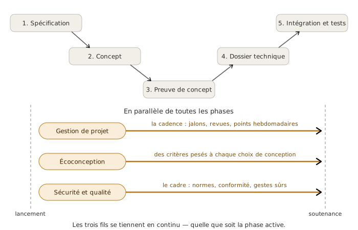
Eco-design is a cross-cutting thread that informs the technical choices made throughout the mechatronics project: assessing their environmental impact, reducing the share of it that comes from electronics and embedded software, recording the decisions in the project deliverables. Like project planning and tracking, it does not start at a particular phase. It settles in continuously, from technical specification through to integration and testing. It connects to the materials and life-cycle assessment courses run by neighbouring disciplines.
The right mindset
The temptation with eco-design is to treat it as a box to tick at the end of the project. A paragraph added to the report about “how recyclable PLA is” and the job is done. Resist it. Eco-design is neither a deliverable, nor a section, nor a side comment: it is a criterion built into the technical choices from the technical specification onwards. The key skill this framework page teaches: questioning every decision from an environmental angle without treading on neighbouring disciplines — carrying what belongs to electronics and embedded software, delegating what belongs to materials or life-cycle assessment to the courses that cover them.
Goal
Keep an eco-design approach alive and built into the technical choices for the whole length of the project:
- an environmental assessment of the structuring choices (eco-criteria matrix, simplified LCA where it is delegated)
- a reduction in impact built into the electronics and embedded software choices (energy frugality, component service life, PCB demountability, software frugality)
- traceability of the decisions in the technical design file and at the final presentation
- an explicit connection to the materials and life-cycle assessment courses run by neighbouring disciplines
All of this runs across the deliverables of the five phases of the V-model, rather than sitting in a deliverable of its own.
Method
Eco-design works on three fronts that are active in parallel from the technical specification through to the final presentation: assessing the environmental impact of the technical choices, reducing that impact in the areas that belong to electronics and embedded software, recording the decisions so that they stay visible for the whole project. These three blocks do not run in sequence. They feed one another and turn continuously.
1. Assessing
Assessing the environmental impact of a technical choice only means something if the assessment can still steer that choice. An assessment run after the decision has been made is left justifying after the fact what has already been settled, at best producing a compliance report, never bending a trajectory. That is why the assessment slots into the first matrix where a decision gets made: the state-of-the-art comparison table of the technical state of the art at technical specification, the decision matrices per subsystem at concept. Assessing later is always possible, but with no leverage on the choices that matter.
The canonical tool carried by this thread is the eco-criteria matrix: 5 environmental criteria × N candidate solutions, built straight into the existing decision matrices as a row or a dedicated block, rather than kept apart in a separate deliverable. That integration is what forces the decision: the environmental criterion weighs as much as cost, performance or service life. An eco-criteria matrix sitting alongside weighs nothing. An eco-criteria row inside the decision matrix weighs exactly as much as the other rows. The simplified LCA rounds out the toolkit for the structuring choices whose scope goes beyond electronics and software: its full method belongs to the materials and life-cycle assessment courses, and this page does no more than name it and point to the course that covers it.
The line between what gets quantified with the reader’s own expertise and what gets delegated is a clear one. On the electronics and software side, the quantities are within reach: power draw in operation (in W or mW), power draw in standby (in µA or mA), indicative service life of the components (cycles, MTBF, announced end-of-life date), mass of copper in the PCB, number of layers. On the colleagues’ side: carbon impact of the raw materials, energy of manufacture, end of life of materials, ISO 14040 LCA standards. The practical rule: if quantifying it calls for a materials or processes skill the team does not have, name the issue and point elsewhere. Do not invent an LCA on the spot.
How often the assessment happens follows the milestones of the project naturally. Initial assessment at the first decision matrix at concept; reassessment at every phase review when a choice flips (a new component retained in the technical design file, an architecture rewired after the proof of concept); final check at the integration and testing review, to confirm that the decisions held at concept have not been quietly wiped out by later component choices.
Example: 3-axis arm project
On the choice of motors at concept (step 2), an eco-criteria matrix of 5 criteria × 3 solutions (steppers / DC with encoders / servo motors) includes a holding power draw criterion quantified in W (steppers draw current while holding, and so do DC motors under a gravity load, unless the transmission is irreversible) and an indicative service life criterion in cycles. The eco-design criterion is not added as a separate column. It weighs on the decision just as much as cost or accuracy. At the PoC review in week 6 the matrix is gone over again: the measured power draw of the steppers matches the order of magnitude that was assumed, and the choice is confirmed without reopening it.
Deliverable 1/3 — Eco-design
Environmental assessment present in the structuring technical choices, evidenced by:
- Ongoing: eco-design criterion built into the decision matrices (step 2 of concept) and into the comparison table of the technical state of the art (step 2 of technical specification)
- At milestones: one eco-criteria matrix per structuring subsystem, presented at the phase review
2. Reducing
Reducing impact happens in the everyday technical choices, not in a separate act of “environmental optimisation” carried out at the end of the project. Four fronts belong to electronics and embedded software expertise and have to be carried by this thread in its own right.
Energy frugality. Size for what is actually needed rather than for a comfortable margin. An oversized motor driver “to keep some in reserve” burns static losses for the whole length of the project. A linear supply chosen for simplicity dissipates as heat what a switching converter would save. On the microcontroller side, use the low-power modes (sleep, deep sleep, hibernation depending on the microcontroller) rather than leaving the core running all the time. The order-of-magnitude sum is immediate: a microcontroller at 50 mA running permanently against 10 µA in deep sleep is a factor of five thousand on the average power draw, as soon as the system spends most of its time waiting.
Component service life. Choose components that will not go obsolete during the service life of the system. Industrial parts (extended range, second source available, datasheet stable for several years) hold up where consumer parts can disappear in two years. Thermal margins are cheap life insurance: a component used at 60% of its maximum temperature lasts significantly longer than one at 95%. The practical rule: prefer a component you can find at two distributors and that has existed for five years over the latest marketing reference whose “in production” status cannot be checked.
PCB demountability. Favour connectors (JST, headers, terminal blocks) over direct soldering for everything that can legitimately be replaced (motors, sensors, power supply, radio modules). Keep the board modular, with functions that can be separated, rather than a monolithic PCB where one fault means replacing the lot. Demountability costs area and BOM, but it changes the repairability and the end of life of the system completely. Think about the silkscreen too: a well-labelled PCB is a PCB you can diagnose without the schematic, and therefore repair.
Software frugality. Embedded code has a direct energy cost. A polling loop that reads a sensor every millisecond keeps the microcontroller awake permanently. The same need served by an interrupt on the sensor leaves the microcontroller asleep between events. More broadly: a microcontroller sized for what is needed (not a Cortex-M7 to blink an LED), libraries compiled with optimisation, an RTOS chosen for its footprint where that is relevant. Software frugality is not a bit of premature optimisation for its own sake. It is an architectural discipline that separates what has to run all the time from what can sleep.
What this thread does not carry: the choice of materials (PLA, ABS, metals, composites, covered by the materials course), manufacturing processes, material recyclability, a full LCA. Those fronts belong to the materials, manufacturing and life-cycle assessment courses. The team names them and brings them in as FC or as risks where relevant, but does not duplicate them in-house.
Example: 3-axis arm project
Four eco-designed choices held on the electronics and software side: ESP32 in light sleep between commands (Wi-Fi stays associated, wake-up in a few milliseconds, power draw of the order of a milliamp while waiting against around 80 mA in nominal operation), JST connectors for the motor and limit switch links (undone with a screwdriver, no soldered wire), motor drivers sized on the actual working current (no systematic oversizing “to keep a margin”), code driven by interrupts on the limit switches rather than by polling (the microcontroller idle most of the time, waiting for an event). The PLA used for 3D printing the structural parts belongs to the materials course and is not decided here.
Watch out
Reducing does not mean pushing one criterion to the extreme. Choosing the microcontroller with the lowest power draw without looking at its availability, its service life or its development ecosystem can make the overall result of the project worse. Impact is reduced through balanced decisions across several fronts (energy frugality, service life, demountability, software frugality), not by over-investing in one. An ultra-frugal component that is obsolete in 18 months weighs more, in total impact, than an average but durable one.
Deliverable 2/3 — Eco-design
Impact reduction built into the electronics and embedded software choices, evidenced by:
- Ongoing: explicit eco-design criteria in the component choices, the PCB architecture and the software structure
- At milestones: at every phase review, a justification of the eco-designed choices on the four fronts (energy frugality, service life, demountability, software frugality)
3. Recording
Traceability is what stops eco-design from staying an intention. Without it, the eco-designed decisions stay in the team’s heads, vanish the moment a component changes mid-project, and shrink to a generic paragraph in the final report. With it, they run through the project as a continuous thread. This traceability is largely steered by project planning and tracking. That is the thread that paces the reviews, keeps the risk matrix, and structures the technical design file. Eco-design fits into that steering: it does not create a cadence of its own, it slots into the one that already exists.
Three traceability practices structure this block.
- Build the eco-design criterion into the decision matrices from concept onwards. Not as a footnote under the table, not as an incidental column, but as a row or group of weighted rows that count as much as the other criteria. This is the most structuring of the three: a criterion that carries weight in the scoring genuinely steers the decision. A criterion that merely appears in the margin steers nothing. The decision matrices become, in this way, the first traceable documents where eco-design leaves a written, dated mark that can be pulled out again when the question comes back.
- Track eco-design risks in the project risk matrix, alongside the technical and schedule risks. Typical ones: a long-service-life component going unavailable, a supplier without the certification it claimed, a material ruled out late by a manufacturing constraint, a dependency on a component at the end of its commercial life. These risks carry the same attributes (likelihood, severity, response) as the others and the same update cadence, revised at every phase review.
- Give the technical design file an eco-design appendix listing the decisions taken and their justification. Simple format: a three-column table (choice made / alternatives ruled out / environmental justification), one row per structuring decision. Not a literary essay, but a factual summary that makes the decisions checkable, and that you can stand behind at the final presentation.
At the final presentation, eco-design comes across as a thread running through the project, not as a section tacked on at the end. The panel, or the teacher, should be able to follow the thread from the first decision matrix at concept, through the choices settled in the technical design file, to the system delivered at integration. Eco-design that has been recorded properly takes a few minutes to present, because it rests on documents produced all the way along. It does not need a slide of its own.
Example: 3-axis arm project
Eco-design appendix of the technical design file: a table of 4 rows (stepper motors chosen, microcontroller deep sleep, JST connectors, PLA chosen for the 3D printed parts) and 3 columns (choice made / alternatives ruled out / environmental justification). The fourth decision (PLA) is explicitly marked “delegated to the materials course”. The page does not argue about the comparative recyclability of bioplastics, it points to the course that covers it for the material justification, and simply files the choice as it was settled with the teacher concerned.
Tip
Eco-design does not need a section of its own. It needs to be visible everywhere. Rather than an “Eco-design” chapter added at the end of the report, put a mention into each section where it makes sense: an eco-design criterion in the comparison table (state of the art), an FC on materials in the pieuvre (the “octopus” diagram, the French function-mapping tool), an eco-design criterion in every decision matrix, an eco-check milestone at the phase review, an appendix of decisions in the technical design file. That spread-out presence is worth more than one concentrated, isolated section.
Deliverable 3/3 — Eco-design
Traceability of the eco-designed decisions held for the whole length of the project, evidenced by:
- Ongoing: eco-design present in the phase reviews and in the risk matrix
- At milestones: an eco-design appendix in the technical design file listing the decisions taken and their justification, presented and defended at the final presentation
Common pitfalls
- Treating eco-design as a chapter at the end of the report. A section added after the fact that weighs on no technical choice is a paragraph for show, not an approach.
- Reducing eco-design to the choice of materials alone, forgetting that it plays out just as much on the electronics side (energy frugality, component service life, PCB demountability) and on the software side (software frugality).
- Treading on the ground of the colleagues’ courses: producing an ad hoc LCA whose method has not been checked by the disciplines that own it, or arguing in-house about the recyclability of materials the team does not master.
- Assessing after the technical choices, when the assessment can no longer steer anything and is left, at best, justifying after the fact what has already been settled.
- Over-optimising a single environmental criterion at the expense of the coherence of the system as a whole. An ultra-frugal component that is obsolete in 18 months weighs more than an average but durable one.
- Confusing eco-design with greenwashing. Recording eco-designed decisions is not a promotional argument, it is engineering data, and it gets justified at the review.
During this phase, on the team side
Eco-design does not work on its own: it connects to the other two cross-cutting threads and delegates explicitly to several courses run by neighbouring disciplines. Three connections structure this section.
Connection with project planning and tracking — an asymmetric mirror. Project planning and tracking steers eco-design just as it steers safety and quality: it builds it into the cadence (a reminder at the phase review), into the risk matrix (eco-design risks alongside the technical ones), into the milestones (an eco-check at the review). So the eco-design thread does not create formal slots of its own. It fits into the cadence that exists. The practical consequence: holding eco-design does not call for extra meetings, but for a dedicated slot at the phase review (five to ten minutes is enough) and an explicit presence in the updated risk matrix. Without that presence inside project planning and tracking, eco-design drifts off the radar within weeks.
Connection with safety and quality — regulatory overlaps. Eco-design crosses safety and quality on the environmental standards (RoHS, REACH, WEEE in particular), which have both a compliance dimension (carried by safety and quality) and a dimension that steers the technical choices (carried by eco-design). The non-overlap rule is clear: safety and quality carries regulatory compliance in the strict sense — identifying the applicable standards, recording that they are met, the CE declarations — and eco-design carries the technical decisions that follow from the corresponding constraints (choosing an alternative to a component containing a substance restricted by REACH, for example). When a point sits on the boundary, the reflex is to handle it in both threads from two different angles, rather than in one at the expense of the other.
Explicit delegation to the colleagues’ courses. This is a strong feature of eco-design: a large part of the field belongs to neighbouring disciplines and has to be handed over without hesitation. Carried elsewhere: the choice and characterisation of materials (PLA, ABS, metals, composites, covered by the materials course), manufacturing processes and their impact (machining, 3D printing, soldering, covered by the manufacturing course), full life-cycle assessment to ISO 14040 (a dedicated LCA course), detailed environmental standards beyond RoHS, REACH and WEEE. The eco-design thread names each of these fields whenever a decision touches them, but does not duplicate them in-house. A student who produced an ad hoc LCA without a check from the course that owns it builds an argument that the final presentation will show up for what it is.
Wrap-up
By the end of the project, eco-design will have run through the five phases of the V-model without ever being a section or a separate deliverable. It will have taken shape in the technical choices, in the decision matrices, in the risk matrix, in the technical design file. Eco-design done well does not show as an add-on. It is measured by how coherent the decisions stay from an environmental angle across the whole project. See the project path hub to place this framework page back in the V-model as a whole, and the project planning and tracking and safety and quality pages for the other two cross-cutting threads it works alongside.
See also
- Project path hub
- Eco-criteria matrix (the canonical tool of this thread)
- Écodesign (sister concept page: the design approach against the engineering approach, the PROJ/5 criterion)
- Simplified LCA (the full version is delegated to the colleagues’ courses)
- Decision matrix (carries the eco-design criterion)
- Project planning and tracking (cross-cutting thread, steers eco-design)
- Safety and quality (cross-cutting thread)