The technical specification is the first phase of a mechatronics project: it turns a need expressed in everyday language (“we would like a robot that…”) into a quantified reference document, the cahier des charges fonctionnel (CdCF), the French functional requirements specification. This is the phase that decides what has to be done, before any choice of technical solution.
The right mindset
The temptation at this stage is to jump straight to components: “we will need an ESP32, a temperature sensor, a stepper motor”. It has to be resisted. This phase does not ask for the solution to be imagined, it asks for the problem to be understood. The more precise the need is here, the less backtracking there is later. A rushed specification costs more in correction time at the end of the project than it does at the start.
Goal of this phase
Produce a functional requirements specification (CdCF) that:
- states unambiguously what the system must do (and not how)
- puts figures on every requirement (criterion, level, flexibility)
- builds in the eco-design constraints
- rests on a technical state of the art
- is approved by the client or the project sponsor
This document serves as the reference for the whole project and as the final assessment grid: at delivery, the CdCF is gone through point by point to accept or reject each requirement.
Method
1. Analyse the need
Before any drawing or choice of component, what is really being built, and for whom has to be understood. This is the step that gets rushed most often, and the most costly one to rush: a need that has been misread produces a system that works but serves no purpose.
Analysing the need runs in three stages: setting the context, stating the need with the bête à cornes, checking that it is understood.
Depending on the project, a scoping note may be handed out by the teaching staff. In that case you are not “discovering” the need. You restate it to show that you have understood it, and you make it precise wherever it is not explicit. The method stays the same.
Set the context
The context answers one question: why does this project exist?
To cover in the report:
- Origin of the project — who is asking for it, why now, what initial situation motivates it
- Stakeholders — who is affected (end user, client, maintainer, manufacturer, neighbours, the environment)
- Technological barriers — what technical or scientific obstacles the project sets out to overcome
Watch out
A technological barrier is not a personal difficulty. “We have never made a PCB” is not a technological barrier, it is a gap in experience that the team will close during the project. A real barrier: “detect a flammable gas at a concentration below 50 ppm, with a component costing under €10 in volume production”. If the project carries no strong technological barrier, say so honestly and move the challenge elsewhere (system integration, industrial constraints, performance).
State the need with the bête à cornes
The bête à cornes (the “horned beast” diagram, the French need-statement tool) is the canonical tool of standard NF X50-151 for expressing a need formally. It forces three answers:
- Who does the system serve? → the user, in the broad sense
- What does it act on? → the object, substance or medium it operates on
- To what end? → the service delivered
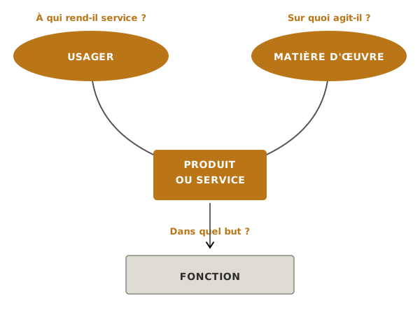
Example: incubator project
- Who: an amateur poultry keeper aiming for self-sufficiency in food
- What it acts on: fertilised hen eggs
- To what end: bringing the embryos through to hatching without constant supervision
Special case: a school project with no real client
Many teaching projects have no external client and will be taken apart after the final presentation (maze-solving robot, sumo robot, and so on). The bête à cornes then looks like it is running on empty.
Two honest positions, depending on the project:
- The students become their own client: the service delivered is a set of targeted skills (“build a control loop, integrate a custom electronic board, tune a PID controller”). The “who” is the team itself, and the “to what end” is explicitly a teaching goal. That holds up at school, not on a professional project.
- The team gives itself a credible fictional client: for the maze robot, a use case can be imagined (“robot for inspecting buried pipework”). The functional analysis becomes coherent, and the exercise takes on a realistic engineering dimension.
Pick one of the two positions explicitly and hold it for the whole of the CdCF.
Example: 3-axis arm project
The running example of this wiki, a 3-axis teaching robot arm, falls under the students-as-their-own-client position: the sponsor is the mechatronics teacher, and the service delivered is explicitly a teaching one (a demountable, reproducible platform for teaching a complete control loop).
- Who: a mechatronics teacher looking for a reusable teaching platform
- What it acts on: light objects (≤ 100 g) to be moved within a reachable working volume
- To what end: illustrating a complete mechatronics project method on a system that is simple, demountable and reproducible
Check that the need is understood
Once the bête à cornes is written, put it to the test:
- Open brief (the need was built by the team): check it with the real client or their representative. If the wording surprises the client, it has been misread.
- Framed brief (a scoping note was handed out): check it against that document. Is there anything in the brief that does not appear in the bête à cornes? Are there choices the team has made that the brief does not justify?
This check leaves a written trace (an email, minutes of a meeting, or a dedicated section of the CdCF). It is the proof that everyone reads the need the same way. Without it, the team is working on assumptions.
Tip
The bête à cornes looks trivial, and that is exactly where its power lies. Three questions, three answers: it looks like child’s play. But putting into three lines what everyone thought was obvious brings out the disagreements hidden inside the team, or with the client. The moment two teammates answer the “who” differently is exactly the moment the tool earns its keep.
Deliverables 1/6 — Technical specification
- Written context for the project (origin, stakeholders, technological barriers)
- Bête à cornes diagram for the project
- Written trace of the need being checked (email, minutes of a meeting, or a dedicated section of the CdCF)
2. Study what already exists
The need is understood and checked. Before putting figures on what the system must do, look at what is already out there. Nobody designs in a vacuum: for almost any mechatronics project, commercial products, open-source projects or earlier student projects have already addressed a similar need. Studying them turns up reusable building blocks, calibrates realistic orders of magnitude, and avoids reinventing something that already works.
This work produces a technical state of the art: a quantified comparison of existing solutions against chosen criteria. It runs in three stages: listing the solutions, defining the criteria, comparing and concluding.
Watch out
A technical state of the art is not a literature review. A literature review means reading (papers, datasheets, standards, books) and producing notes. A technical state of the art means listing what exists and works, and producing a quantified comparison aimed at a decision. Each feeds the other, since the reading supplies the raw material, but they are not the same deliverable. A state of the art that is only a list of papers read is not a state of the art.
List the existing solutions
Identify 3 to 6 comparable references that address a need close to yours, even partly. No more than that: beyond six, the analysis thins out. No fewer: with 1 or 2 solutions there is nothing to compare.
Sources to work through systematically:
- Commercial products — manufacturer catalogues, distributor sites, datasheets
- Open-source projects — GitHub, Hackaday, Thingiverse, Instructables, the Open Hardware Repository
- Short academic publications — conference papers, final-year dissertations, technical articles written for a general audience
- Earlier student projects — the school archives, and any lessons learned that are available
For each reference kept, note the name, the source or URL, the main known figures, and the status (in production, at project stage, abandoned). This first pass can be broad, since filtering by relevance comes next.
Define the comparison criteria
Choose 5 to 8 quantifiable criteria that make sense for the project, anchored on the need written at step 1. The criteria have to tell the solutions apart: a criterion on which every solution scores the same brings nothing.
Families of criteria to consider:
- Cost — to buy, to build, to maintain (almost always present)
- Main performance — the target quantity of the system (accuracy, throughput, battery life, payload, depending on the project)
- Constraints of use — size, mass, power draw, robustness, safety
- Eco-design — origin and recyclability of the materials, durability, demountability, repairability
- Openness — availability of the BOM, the firmware, the schematics (decisive if building blocks are to be reused)
The criteria kept here prefigure the ones that will carry figures at step 4, in the CdCF. Chosen well, they make step 4 markedly easier.
Compare in a table
Cross solutions and criteria in a table of N solutions by M criteria (solutions in columns and criteria in rows usually reads better). Use figures (“250 g”, “0.1 mm”, “€180”). No empty cells: a missing figure is written “n/a” or ”?”, and its absence becomes information in itself.
The table on its own is not enough. Conclude in a few lines: what is being taken from this? Which solutions inspire the architecture being considered? Which are being ruled out, and why? What orders of magnitude come out of the comparison and will serve to calibrate the CdCF?
Example: 3-axis arm project
Three comparable references were kept:
Criterion Niryo One uArm Swift Pro BCN3D Moveo Cost ~€3,000 ~€600 ~€300 (materials) Payload 500 g 500 g 250 g (estimated) Repeatability 0.5 mm 0.2 mm 1-2 mm (estimated) Openness (BOM/firmware) partly open closed fully open What is taken from this: Moveo is the most inspiring reference (open, demountable, affordable, 3D-printable structure). Its general logic is reused, but simplified from 6 axes to 3 to stay within a teaching scope. Orders of magnitude calibrated for the CdCF: aim for ~€300 of materials, a payload of 100 g (a deliberate reduction, given the 3 axes), and accuracy of ± 5 mm at the end of the arm (acceptable for a teaching demonstrator).
Deliverable 2/6 — Technical specification
- Technical state of the art: a quantified comparison table of 3 to 6 solutions by 5 to 8 criteria, together with a short synthesis paragraph (“what we take from this”) and a short bibliography of the sources consulted.
3. Formalise the functions
The need is understood and the existing solutions are mapped. What the system must do now has to be formalised, still without assuming how. The canonical tool of standard NF X50-151 for that is the pieuvre (the “octopus” diagram, the French function-mapping tool). It forces you to identify first what the system interacts with (the surrounding media), then which services it must deliver, sorting the functions into three categories: main functions (FP), secondary functions (FS) and constraint functions (FC).
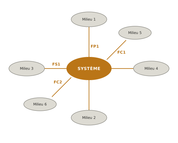
Identify the surrounding media
List every external element the system is in contact with: material, energy, information, people, physical environment. Method: build a mind map of the system in its real setting, starting from the system at the centre and listing all around it whatever touches it, powers it, watches it or has to put up with it. No filtering at this stage. A medium left out is a function that will never appear in the CdCF.
A few families of media to work through systematically:
- Users — operator, maintainer, exposed bystander
- Object acted on — the object or substance the system works on
- Energy sources — mains power, fluid, consumable resource
- Physical environment — temperature, humidity, vibration, supporting structures
- Regulatory — applicable standards, safety or eco-design constraints
State the main, secondary and constraint functions
Once the media are identified, draw the links of the diagram. Each link is a function, to be written as an infinitive verb plus complement and numbered so that it can be referred to later.
- FP (main function) — links two media through the system, and justifies its existence. It is the product’s reason for being. Without an FP, the system has no purpose.
- FS (secondary function) — also links two media through the system, but answers a desirable extra service, not one essential to the mission. Without an FS, the system still does its job. With an FS, it does the job better.
- FC (constraint function) — links the system to a single medium. It expresses a constraint of adaptation (“withstand”, “fit”, “be compatible with”). Standards, eco-design and constraints of use often turn into FC.
Watch out
A function expresses a need, never a solution. The classic trap is writing FP1 = “use a Raspberry Pi to drive the motors”. That is not a function, it is a premature technical choice. The right wording would be: “command the actuators in response to the operator’s instructions”. Rule of thumb: if a brand, a component or a technology can be named in the wording, something has gone wrong.
Example: 3-axis arm project
The pieuvre covers the physical system (the arm and its interactions). The bête à cornes of step 1 covered the teaching brief above it (the teacher as sponsor, the service delivered being the illustration of a project method). The two levels coexist within the students-as-their-own-client position and do not contradict each other. They simply do not describe the same system.
Surrounding media identified: the object to be moved, the operator, a computer, the mains supply, the teaching environment (fablab, accessible means of manufacture).
Functions stated:
- FP1 — Allow the operator to handle the robot so as to place a light object at any point of the working volume.
- FS1 — Allow the operator to program a sequence of movements from a computer.
- FC1 — Fit the mains supply available (230 V through an adapter).
- FC2 — Be demountable and reproducible with the means of a school fablab (3D printer, drill, screwdriver).
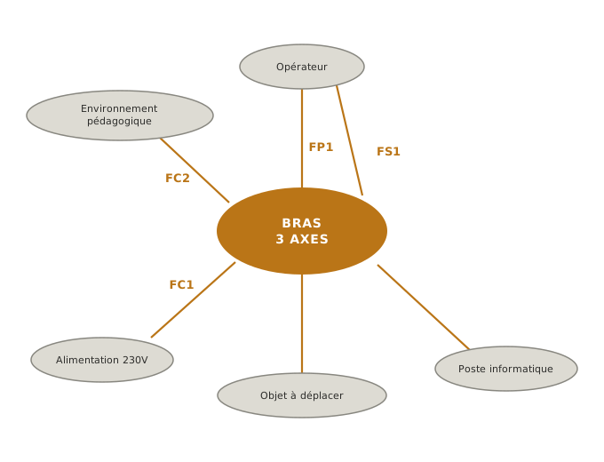
Stating the functions says nothing about the levels expected or the flexibilities. At this stage, FP1 says that a light object has to be placed, not how much it weighs or to what accuracy. That is exactly what the next step is for: characterising each function through a criterion / level / flexibility triplet.
The pieuvre gives the what. The how, meaning which technical functions the system will use to deliver those service functions, will be broken down through FAST in the next phase, concept, when the architecture is chosen.
Deliverables 3/6 — Technical specification
4. Characterise the functions
Stating a function is not enough. It still has to be made quantifiable, measurable and opposable, that is, capable of being held against the supplier if it is not met. This step turns each function (FP, FS, FC) coming out of the pieuvre into a quantified requirement, by applying the criterion / level / flexibility triplet of standard NF X50-151 systematically. It is the most structuring step of the phase: without quantified characterisation, the CdCF is only a statement of good intentions, and assessing the project at the end becomes impossible.
Three questions to ask for each function. The method itself is covered in the characterising a requirement tutorial.
State the criterion
The criterion is the quantifiable, observable attribute the function will be judged on. A good test while writing: can a measuring set-up be imagined? If not, the criterion is the wrong one.
Families of criteria to draw on:
- Physical quantities — mass, length, speed, accuracy, temperature, power, battery life
- Economic quantities — purchase cost, maintenance cost, return on investment
- Time quantities — service life, MTBF, response time
- Binary quantities — present or absent, compliant or not with regulations
Choose the criterion that really tells solutions apart, not an abstract proxy. “Ergonomics”, “pleasant”, “high-performing” are not criteria. They are intentions, and they have to be turned into measurable quantities (“actuation force below 5 N”, “learning time under 10 min”).
Set the level
The level is the target figure the criterion has to reach. Always a figure, always with a unit. The level is built at the meeting point of two sources:
- The need written at step 1 — what the system has to do for its user
- The orders of magnitude found at step 2 — what existing solutions already manage
The level takes several forms, depending on the criterion: a single value (100 g), a bound (≤ 5 mm, ≥ 50 mm/s), or a range (between 20 °C and 30 °C).
One precaution: do not be more precise than the real need. A level of ± 0.1 mm where ± 5 mm would do brings nothing usable and sends the cost through the roof.
Define the flexibility
The flexibility says two things: how much margin is tolerable around the level, and how far that margin is negotiable. Two complementary parts:
- The numerical tolerance — the concrete deviation allowed around the level (
± 0.5 mm,± 5%) - The negotiability level Fn — the four-step qualitative scale of NF X50-151:
- F0 — Mandatory: not negotiable. If the level is not reached, nothing gets delivered. Typical of safety requirements and of regulatory compliance.
- F1 — Barely negotiable: a deviation is tolerable against a strong compensation (a substantial gain on another criterion).
- F2 — Negotiable: a deviation is acceptable if it is justified and ruled on.
- F3 — Very negotiable: a comfort value, where a deviation is not blocking.
What the Fn does in practice is say how the trade-off will be made in the event of a conflict (between requirements, against the budget, against the schedule). Without an explicit flexibility, every deviation during the project turns into a crisis. With one, it is a trade-off that was planned for.
Watch out
An unquantified level is a requirement that cannot be held against anyone. A CdCF that states “the system must be accurate” or “the cost must be reasonable” is unusable. At delivery, how is it assessed? Accurate according to whom, reasonable compared with what? The requirement is neither measurable, nor contractual, nor assessable. Every line of the CdCF has to carry a figure. That discipline is what turns a statement of good intentions into a document that holds up, one that works both as a compass during the project and as the final assessment grid.
Tip
Quantified requirements are written in SI units. Symmetrical tolerances:
± X mm. Bounds:≤ Xor≥ X. Ranges:between X and Y. This discipline is not a writing affectation. It heads off ambiguities (100mmbroken across a line end,100m mretyped without a second look) and makes requirements directly comparable in review.
Example: 3-axis arm project
Full characterisation of FP1 — “Allow the operator to handle the robot so as to place a light object at any point of the working volume”:
- Criterion — positioning accuracy at the end of the arm
- Level — ± 5 mm anywhere in the reachable working volume
- Flexibility — F1, tolerance up to ± 10 mm in exchange for a substantial saving
Justification: ± 5 mm is calibrated on the comparison from step 2 (the Moveo arm goes down to 1-2 mm, but with a complexity outside the teaching scope, and the uArm Swift Pro at 0.2 mm is out of reach on this budget). F1 reflects how central accuracy is to the demonstration purpose, while still allowing some slack if the mechanical cost of going finer becomes disproportionate to the teaching benefit.
Once the triplet is set down properly, assessment at the end of the project is simple: measure the real accuracy of the prototype, set it against the ± 5 mm target, and the documented deviation (measured, explained, ruled on) becomes material for the final report. It is not a failure, it is an engineering result.
Deliverable 4/6 — Technical specification
5. Plan the project
The what is settled: what the system has to do, and how it will be assessed. What remains is to organise the when and the who. Project planning is built at the end of the technical specification, because you cannot plan what has not been defined yet. It then lives on for the whole project, and is brought up to date at every phase review.
On a school project, planning has one particular feature: the end date is imposed by the academic calendar (final CdCF review, final presentation, exam timetable). You do not plan forwards from today to work out an arrival date. You plan backwards from a known arrival date to today. That is backward planning.
Break the work down into a WBS
The WBS (work breakdown structure) splits the project into traceable items, from the overall deliverable down to elementary tasks. Two or three levels of depth are enough at school: phase, then sub-deliverable, then concrete task. Beyond that, the team gets lost in administration and loses the overall view. The WBS acts as a shared reference for splitting the work across the team and for making sure no structuring task has been forgotten.
Place the work in the calendar
Once the tasks have been identified through the WBS, three complementary tools put them on the calendar.
Milestones are the approval points that give the project its rhythm. They mark the transition between two phases of the V-model (CdCF approved, PoC conclusive, technical design file approved, integration delivered, final presentation) and gate the move to the next one. A missed milestone is not something you catch up by working harder the following week. It pushes everything downstream.
Backward planning means putting the milestones on the calendar first, starting from the end and working back, then fitting the WBS tasks between those milestones. It is the timeline skeleton of the project.
The Gantt chart makes that plan visible: tasks in rows, calendar in columns, horizontal bars showing durations and overlaps. Its teaching strength is that it brings out the dependencies (this task is waiting on that one) and the bottlenecks (this week has far too much work in it).
Several tools are usable: a spreadsheet or paper (quick to set up, enough for a simple Gantt), GanttProject (free dedicated software, handles dependencies well), Trello (online, handy for the WBS and for day-to-day task tracking). Pick one tool and stick to it. The worst outcome is planning scattered across three supports that have drifted out of sync.
Keep the risks under control
Every project meets its share of setbacks: a component out of stock, a 3D printer down, a teammate away, a technical building block that turns out to be harder than expected. The risk matrix is about anticipating them before they happen: identify the main risks, rate them by likelihood and severity, and decide on a response for each (prevention, mitigation, fallback plan).
At school, 5 to 10 major risks are enough. More than an exhaustive list, what counts is keeping it current. The risk matrix is reread at every phase review and updated whenever a new risk appears or an old one is cleared.
Watch out
A plan that is never updated lies. Planning is not a start-of-phase deliverable to be filed away afterwards. It is a living tool, and it is only worth something if it reflects the real state of the project. A team that produces a fine Gantt chart in week 2 and never opens it again until week 14 has wasted its time. Conversely, a Gantt chart brought up to date every week, imperfect as it may be, becomes a powerful steering tool: it reveals drift early, while there is still room to act.
Tip
Put the date of the final presentation down first, then work back while keeping some margin. Naive backward planning stacks the tasks end to end right up to the eve of the presentation. One unforeseen event, and there is always one, and the whole thing overflows. Keeping at least two weeks of margin before the deadline, set aside for finishing the report and rehearsing the presentation, changes the nature of the project: the stress stops being systemic and becomes occasional.
Example: 3-axis arm project
Milestones set (on a 15-week project):
- W3 — CdCF review
- W6 — PoC conclusive (stepper motors synchronised, mechanical endurance of one joint validated)
- W11 — Technical design file approved, orders placed
- W14 — Integration and testing finished
- W15 — Final presentation
WBS at level 2 (extract): Mechanics (articulated structure, joints, assembly), Electronics (driver board, wiring, power supply), Software (stepper control, PC interface, PC-to-board communication), Project (CdCF, technical design file, final report).
Major risks identified (5):
- Mechanical endurance of the 3D-printed joints — medium likelihood, high severity → oversize them and test early on a single joint.
- Synchronisation of the 3 stepper motors — medium likelihood, medium severity → validate the software-to-driver interface as early as the PoC.
- Fablab unavailable during exam weeks — high likelihood, medium severity → schedule the critical prints before W10.
- PC interface more complex than estimated — medium likelihood, low severity → a minimal command-line version as a fallback.
- Teammate unavailable (placement, illness) — low likelihood, high severity → pair up on the critical tasks to avoid single points of knowledge.
Deliverables 5/6 — Technical specification
- WBS of the project (2 to 3 levels of depth)
- Backward plan drawn as a Gantt chart, with the key milestones of the V-model
- Risk matrix (5 to 10 major risks, rated by likelihood and severity, each with its response)
6. Write the CdCF
The five previous steps have produced all the material of the CdCF: the need analysis, the state of the art, the pieuvre, the characterised functions, the plan. What remains is to bring them together into a single document, structured, opposable and fit to be presented in review. This step produces no new material. It organises and lays out what already exists, so as to produce the reference document of the project.
The version taught here is a simplified school version, a recognisable derivative of standard NF X50-151. It gathers the deliverables of the five previous steps into one document, while explicitly distinguishing the normative core (functional analysis in the strict sense) from the school additions (state of the art, planning), which are not formally part of a CdCF in a professional setting but belong here for teaching coherence.
Structure the document
The simplified school CdCF is organised in five sections, following the order of the five previous steps:
- Presentation of the project — context, stakeholders, system boundary (material from step 1)
- Statement of the need — bête à cornes, need checked (material from step 1)
- Study of what exists (school addition) — technical state of the art, comparison table, synthesis (material from step 2)
- Functional analysis (core of NF X50-151) — pieuvre, table of characterised functions (material from steps 3 and 4)
- Project plan (school addition) — WBS, Gantt chart, risk matrix (material from step 5)
The order follows the teaching sequence of the phase, which makes for natural reading by someone discovering the project. The sections are labelled explicitly, “core of NF X50-151” on section 4 and “school addition” on sections 3 and 5, so that the student, and the student’s reader, can tell the normative core from the additions.
A pre-filled Word template is provided in the repository to get the writing started: cdcf-ecole-template.docx. The document is in French, like the diagrams of this wiki. It carries the five-section table of contents, with a cover page, an automatic contents list and the tables already laid out (bête à cornes, comparative state of the art, characterisation of the functions, risk matrix). All that is left is to fill in the placeholders in square brackets.
Worth knowing
In a professional setting, a strict NF X50-151 CdCF is limited to the functional analysis (sections 2 and 4 above). The technical state of the art and the project plan are separate deliverables, produced in parallel and aimed at different readers (the technical team, the project management). The formal “response framework” of NF X50-151, the chapter setting out how a supplier is to answer the call for tenders, has no direct equivalent at school: the project plan takes its practical role, framing what comes next rather than organising a supplier consultation.
Write each section
The material of each section already exists. The work here is to bring it together into a single coherent document, taking care over three things:
- The layout. Contents list, page numbers, running heads, numbered sections, clean tables, captioned diagrams. The substance has been validated by the previous steps. The form conveys how seriously the work was done, and makes reading in review easier.
- Coherence between sections. A requirement quantified at step 4 has to be consistent with the order of magnitude retained in the state of the art at step 2. A risk identified at step 5 has to echo an FC from the pieuvre or a barrier raised in the need analysis. Writing the CdCF is the moment to reread the whole thing and correct the leftover inconsistencies that the successive steps had not exposed.
- Working eco-design in. Eco-design is not a section tacked on at the end. It is woven through every section: into the need analysis (stakeholders, including the environment), into the state of the art (the eco-design criterion of the comparison table), into the pieuvre (an FC on materials or end of life), into the plan (eco-check milestones). Writing the CdCF is the moment to check that this really is present everywhere, and not as a cosmetic appendix. Not to be confused with écodesign, the French design-discipline sense of the word, which is usually left to the design courses: the CdCF carries eco-design in the quantified engineering sense, not écodesign. Confusing the two means dealing with only half of the environmental question.
Get the CdCF approved in review
The finished document is presented at the CdCF review, the milestone closing the technical specification in the project calendar. The review is run by the teaching staff, who play here, in the school setting, the role the client plays in a professional one. It has two functions: approving the document (quality, coherence, whether every requirement carries figures) and clearing the move to concept.
To prepare for it:
- Do a final systematic self-review, putting yourself in the place of a reader discovering the document.
- Check that every requirement carries figures (a measurable criterion, a level with a unit, an explicit flexibility). A requirement without figures is the first thing that will be questioned in review.
- Anticipate the questions: why this level and not another? why this flexibility? what happens if an FC is not met?
Two outcomes are possible at the end of the review. CdCF approved clears the move to concept. CdCF to be reworked means corrections before it is presented again. Either way, the feedback from the review is recorded in writing (minutes of the meeting, or comments on the document) and commits the project: whatever was approved in review is not reopened afterwards. That is precisely what the milestone is for.
Watch out
A CdCF is not a copy-paste of the intermediate deliverables. When five steps have produced five batches of pages, the temptation is to staple the lot together and add a cover page. What comes out of that is a compilation, not a document. The repetitions are still there, the transitions are missing, the inconsistencies between sections go unnoticed. The move at step 6 is precisely to reread the whole thing and rewrite whatever needs rewriting, so that the five sections form a coherent account rather than a stack.
Example: 3-axis arm project
The CdCF for the 3-axis arm is organised in the 5 standard sections. Section 1 restates the students-as-their-own-client position settled at step 1 (sponsor = the mechatronics teacher, teaching goal made explicit). Section 4, the core of NF X50-151, gathers the pieuvre and the table of characterised functions: 1 FP, 1 FS, 2 FC, all carrying figures (accuracy ± 5 mm at F1, programming from a computer at F2, 230 V supply at F0, fablab demountability at F0).
Eco-design is woven through: an “openness / repairability” criterion in the state-of-the-art table (section 3), FC2 on demountability in the pieuvre (section 4), the “fablab availability” risk in the risk matrix (section 5). There is no dedicated eco-design section. The environmental question runs through the whole document.
The CdCF is presented at the CdCF review, approved by the teaching staff, and the project moves officially into concept.
Deliverable 6/6 — Technical specification
- Complete functional requirements specification, structured in 5 sections (presentation, need, existing solutions, functional analysis, plan), careful in its form and coherent between sections, presented and approved at the CdCF review.
Common pitfalls
- Jumping to the solution before the need has been written down. The reflex of “we will need an ESP32, a temperature sensor…” from week 1 produces solution-driven CdCFs that turn out to be a poor fit once the real need analysis emerges later. The discipline is to keep the what separate from the how until the end of the phase.
- Confusing a technological barrier with a team’s own difficulty. “We have never made a PCB” is not a barrier, it is a gap to be closed. A real barrier resists even a competent, well-equipped team. That is what justifies an engineering project rather than a simple assembly job.
- An unquantified level. “The system must be accurate”, “the cost must be reasonable”: with no value and no unit, the requirement cannot be held against anyone. It can neither be assessed at the end of the project nor traded off along the way. Every line of the CdCF has to carry a figure.
- A subjective or unmeasurable criterion. “Ergonomic”, “pleasant”, “robust” are not criteria but intentions. They are to be reworded systematically as measurable quantities (maximum actuation force, MTBF, allowable temperature range, learning time, and so on).
- Over-specification. Setting a level finer than the real need (
± 0.1 mmwhere± 5 mmwould do) brings nothing usable, sends the cost through the roof and needlessly complicates trade-offs during the project. The right level is the one that lets the system deliver its service, not the tightest one you know how to write. - Taking F3 for the absence of a requirement. F3 does not mean “not important”: it is a formally quantified requirement whose deviation is tolerable and negotiable. A requirement with no
Fnat all, on the other hand, cannot be held against anyone. The flexibility is a full part of the triplet, not an optional extra.
During this phase, on the team side
Interfaces with other subjects: mechanics and manufacturing. The technical specification happens on paper, but the manufacturing constraints have to be anticipated from now on. Talking early to the mechanics and manufacturing teachers makes it possible to set realistic FC (“compatible with the means of the school fablab”, “machinable on the CNC lathe available”, “3D-printable in one piece under 200 mm”) and avoids discovering during the technical design file phase that the architecture roughly sized at concept cannot be built. Without going as far as freezing the solution, the team has every interest in checking the orders of magnitude of the available materials and processes with the teachers concerned before the CdCF review.
Project planning and tracking. The end of this phase sets the whole steering machinery of the project in motion. Planning (step 5) is not just about producing a Gantt chart. It structures how the team works: who follows which sub-deliverable, who maintains the backward plan, who keeps the risk matrix current. The first weekly check-ins are set up at this point, in a light format (15 minutes, a round-table, blocking points) that will firm up as the project goes on. The project planning and tracking page covers the cross-cutting practice.
Eco-design. Eco-design is not a separate thread to be switched on later. It takes root as early as the technical specification, through seeds spread across the deliverables: an eco-design criterion in the comparison table of the state of the art, an FC on materials or end of life in the pieuvre, risks tied to availability or durability in the risk matrix. A CdCF with no eco-design anchor at this stage produces a project that will not be able to make up for the omission later without reopening the CdCF itself. The eco-design page covers the cross-cutting method.
Safety and quality. Safety and quality start in this phase with a regulatory survey: which standards apply to the system being considered (low voltage, machinery, exposure of the public, CE conformity)? Which safety thresholds cannot be avoided? These translate into FC in the pieuvre at step 3, with flexibility F0 (mandatory) on everything that comes from regulation. Doing it in this phase saves the team from discovering at integration a blocking standard that should have steered the concept. The safety and quality page covers the cross-cutting practice.
Wrap-up
At this point the need is understood and checked, the existing solutions are mapped, the functions are formalised and characterised in figures, and the project is planned. The functional requirements specification is written: it will serve as the reference for the whole project and as the final assessment grid. The work now moves into concept, to turn this what into a how: choice of architecture, decision matrices, rough sizing.
See also
- Project path hub
- School CdCF template to fill in (Word document, in French)
- Cahier des charges fonctionnel (founding concept)
- Bête à cornes
- Standard NF X50-151 (stub)
- Client relationship
- Project archiving
- Next step: Concept