The pieuvre is the graphical functional analysis tool that formalises what the system must do by linking it to the surrounding environments it interacts with. Each link drawn is a function (main, secondary or constraint) that will later be quantified in the cahier des charges fonctionnel.
What is it for?
The pieuvre formalises the interface between the system and its world before any technical solution is chosen. Where the bête à cornes answers “why the system exists”, the pieuvre answers “what the system interacts with, and what it must do towards each of those things”. It is a change of level of analysis: you move from the overall need to a detailed inventory of services and constraints.
Three connected roles:
- Listing the surrounding environments exhaustively so that no interface constraint is missed. An environment forgotten at this stage cannot be caught up later: it becomes a missing requirement in the CdCF, which will surface late, during integration or testing, when the system no longer fits in its real environment.
- Formalising the functions without drifting towards the solution. By explicitly separating what the system must do (FP, FS) from what it must endure or comply with (FC), the pieuvre forces you to reason in terms of service rendered, not in terms of which component to choose.
- Feeding the quantified characterisation of the next step directly. Each function drawn on the pieuvre becomes a row of the requirements table through the flexibility triplet. The pieuvre is therefore the structuring bridge between the analysis of the need (bête à cornes) and the quantification of the requirements.
How do you build one?
Three stages, in order.
- Identify the surrounding environments with a mind map around the system. Put the system in the middle of a sheet and list all around it whatever surrounds it: users, work object, energy sources, physical environment, regulatory constraints. No filtering at this stage — an environment left out is a function that will not appear in the CdCF.
- Draw the links between system and environments, and word each link as a function in the infinitive verb + object format (see the dedicated page for the detail of the statement format and the pitfalls specific to wording).
- Classify as FP / FS / FC and number them. A link that runs through the system between two environments is an FP or an FS. A link that touches a single environment is an FC. The numbering (FP1, FP2…, FS1…, FC1…) is a stable reference for the whole rest of the project — from the CdCF through to the final assessment grid.
Families of environments to go through systematically
| Family | Typical examples |
|---|---|
| Users | main operator, maintainer, exposed third party |
| Work object | the object, the information, the environment the system acts on |
| Energy sources | electrical supply, fluid, consumable resource |
| Physical environment | temperature, humidity, vibration, mountings, available space |
| Regulations | applicable standards, safety constraints, eco-design constraints, CE conformity |
Going through those five families systematically is what makes the pieuvre robust: it is by forcing yourself to review each family, even the one that looks obviously empty, that you discover the discreet environments that a spontaneous fill-in would have missed.
Diagram topology
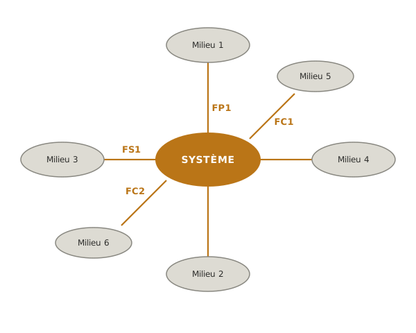
The classic form (AFNOR / NF X50-151 convention) is radial: system at the centre, environments arranged around it, links drawn as spokes. All the links share the same style: the FP / FS / FC distinction is read in the topology (FP/FS run through the system between two environments, FC touches a single one) and in the numbering, never in the line style. That visual uniformity is what makes the diagram readable: an outside reader identifies the category of a function immediately from its geometry, without having to consult a key.
Example — 3-axis arm project
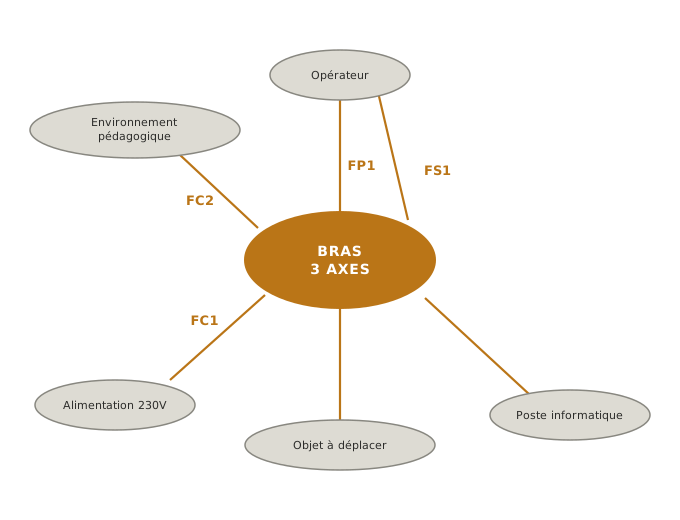
This pieuvre is about the physical system: the robot arm and its direct interactions with its world. It differs from the bête à cornes of the previous step, which was about the teaching commission sitting above the project (the teacher as the sponsor, the service rendered being the illustration of a project approach). The two levels coexist in the students-as-their-own-client stance and do not contradict each other: they simply describe two nested systems.
Five environments identified: operator, object to be moved, computer workstation, electrical supply, teaching environment (fablab and available means of manufacture).
Five functions stated:
- FP1 — Allow the operator to handle the robot in order to position a light object anywhere in the working volume. A main function linking two environments (operator and object to be moved) through the system: it is the reason the arm exists.
- FS1 — Allow the operator to program a sequence of movements from a computer workstation. A secondary function adding a useful service (deferred programming), but without which the arm already fulfils its main mission.
- FC1 — Adapt to the available electrical supply (230 V mains through an adapter). An adaptation constraint linking the system to a single environment: the building’s mains socket.
- FC2 — Be dismountable and reproducible with the means of a school fablab (3D printer, drill, screwdriver). An adaptation constraint towards a single environment: the teaching context of the project.
- FC3 — Preserve the safety of the operator (pinch zones, moving parts). A constraint touching a single environment: the operator, already linked by FP1 on the service-rendered side, here on the risk-incurred side. This is the user-safety FC that the safety and quality thread will follow through to the qualification tests.
At this stage, stating the functions says nothing about the expected levels or the flexibilities. The pieuvre says a “light object” must be positioned, not how much it weighs nor to what precision. That is precisely the role of the next step: characterising each function through a flexibility triplet.
Pitfalls
Forgetting environments. The three families most often skipped: regulations (applicable standards, CE conformity, eco-design constraints), the physical environment (temperature, humidity, vibration, mountings), and energy sources (supply, fluids). The useful move: go explicitly through the five families, even if some look empty: it is by reviewing them that you discover the discreet environments.
Stating a solution instead of a need. The generic pitfall on wording functions is detailed in function: a statement naming a brand, a component or a technology is badly worded. Simple test: “can I replace this statement with another component without changing the meaning?” If you can, it is a need. If the sentence becomes incoherent, it is a disguised solution.
Misclassifying FP / FS / FC. The topology of the diagram must reflect the semantics. A function that touches a single environment but is classified FP/FS is misclassified, or else the second environment is missing from the diagram. Conversely, a function drawn between two environments but classified FC is inconsistent: if it links two environments, it renders a service through the system, hence FP or FS.
Confusing FP and FS. The FP is the reason the system exists. Without it, the project has no purpose. Test: “if I remove this function, does the project still stand?” If it does, it is an FS, not an FP. Many school projects have only one FP. That is normal and rather healthy: multiplying FPs often reveals a badly framed project mixing several distinct objectives.
A radial diagram that cannot be read. Beyond 7 or 8 environments, the radial form becomes unreadable and the links cross each other. Two ways to get some air: (1) group some environments into families (the three RoHS / REACH / WEEE standards can form a single “regulatory environment” instead of three), (2) draw two complementary pieuvres on two levels of the system (a pieuvre of the overall system during specification, local pieuvres per sub-system to be introduced during concept).
See also
- Technical specification — the phase the pieuvre belongs to (step 3)
- Function — FP/FS/FC typology and statement format
- Bête à cornes — the upstream tool that states the need
- Characterising a requirement — the downstream step that quantifies each function
- Cahier des charges fonctionnel — the final document that aggregates the pieuvre and the characterised functions
- Standard NF X50-151 — the methodological framework