Functional breakdown is a top-down analysis that splits a system into coherent subsystems, then each subsystem into internal technical functions, starting from the service functions stated in the cahier des charges fonctionnel (CdCF), the French functional requirements specification. It opens the concept phase by moving the project from an outside view (what the system delivers as a service) to an inside view (how it is organised to deliver it).
What is it for?
The CdCF settles the what of the project. The functional breakdown opens the how by looking, for the first time, at the inside of the system. The traceable internal blocks are identified, and for each block the technical functions that will deliver its share of the service functions. It is the bridge between external functional analysis (service functions coming out of the pieuvre, the “octopus” diagram, the French function-mapping tool) and the exploration of technical solutions discipline by discipline that follows.
The tool plays three inseparable roles:
- Structuring the work of the team, by producing subsystems with clean interfaces that each discipline (electronics, mechanics, software) can take on without blocking the others
- Preparing the exploration of solutions, by bringing the system down to elementary technical functions, each of which can be set against 2 to 5 candidate solutions in a decision matrix
- Revealing the holes in the CdCF — this is the first time the system is looked at from inside, and the service functions that were forgotten nearly always surface at that point
The split produced here is not frozen for all that. Exploring the solutions at the next step can reveal that a block has to be divided (two very different control logics coexist in it) or merged (two blocks in fact share the same structure). Go back and fix it without hesitation.
Step by step
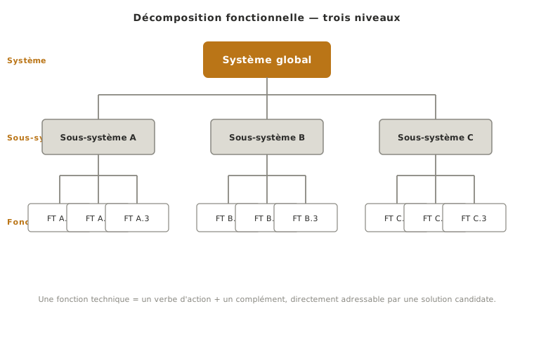
The breakdown runs in two top-down passes — from the overall system to the subsystems, then from each subsystem to its internal technical functions — and closes with a choice of depth. The result is naturally shown as a top-down tree, root at the top.
1. From system to subsystems
At the root, the overall system. At the first level down, 3 to 5 subsystems which, assembled, deliver all the service functions stated in the CdCF. More than 5: the split is too fine for this level, and the technical functions have already been entered. Fewer than 2: the system has not been broken down, it has only been renamed.
Three criteria for a good split:
- Clean interfaces — for each subsystem, it must be possible to list the flows in and out (energy, information, material). If a boundary is fuzzy, so is the split, and the rest of the project will pay for it.
- Technical independence — a subsystem has to be workable by a small group without blocking everyone else on everything. Practical test: can two students make progress in parallel on two subsystems without syncing up every day?
- Comparable size — a subsystem that on its own accounts for 80% of the project has not been split far enough, or the others have been overrated. The imbalance is a signal to reread, not something to accept.
The split is not a division by discipline. A good mechatronics subsystem generally draws on electronics, mechanics and software together. Reproducing the org chart of the team (“the mechanics block, the software block, the electronics block”) misses the functional breakdown: what gets broken down is skills, not the system.
2. From subsystems to technical functions
Under each subsystem, list the internal technical functions that deliver its share of the service functions. The wording follows the convention of the service functions strictly: an action verb in the infinitive plus a complement (“measure the angular position”, “convert electrical energy into movement”).
The conceptual distinction is crucial and often muddled:
- A service function (coming out of the pieuvre) says what the system delivers to the outside. It faces use.
- A technical function (coming out of the breakdown) says how the system goes about it internally. It faces delivery.
The same service function can be delivered by several combinations of technical functions. That is exactly what opens the space of solutions explored at the next step.
3. Stop at the right level
The practical rule: go down as long as the technical function cannot be addressed directly by a candidate solution, and stop as soon as it can. “Measure the angular position” can be addressed (position sensor, incremental encoder, potentiometer and so on) → stop there. “Manage the movement” cannot (too vague to list 2 to 5 concrete solutions) → refine one level.
On a school project, 2 to 3 levels are enough in most cases: system → subsystems → technical functions. Going deeper means anticipating the technical design file and committing prematurely to a component. That choice should be made later, once a decision matrix has settled it.
The split is built over several passes, not in one go. A first high-level pass to set the general structure, then refinement as the exploration of solutions turns up missing or redundant technical functions. Aiming for completeness on the first attempt wastes time and prematurely freezes a split that is going to change anyway.
Example — 3-axis teaching arm
Back to the 3-axis teaching robot arm, whose main function FP1 (fonction principale, the main function of the pieuvre) reads: “allow the operator to handle the robot so as to position a light object at any point of the working volume”. Three possible splits, from the unusable statement to the breakdown that can be used directly at the next step.
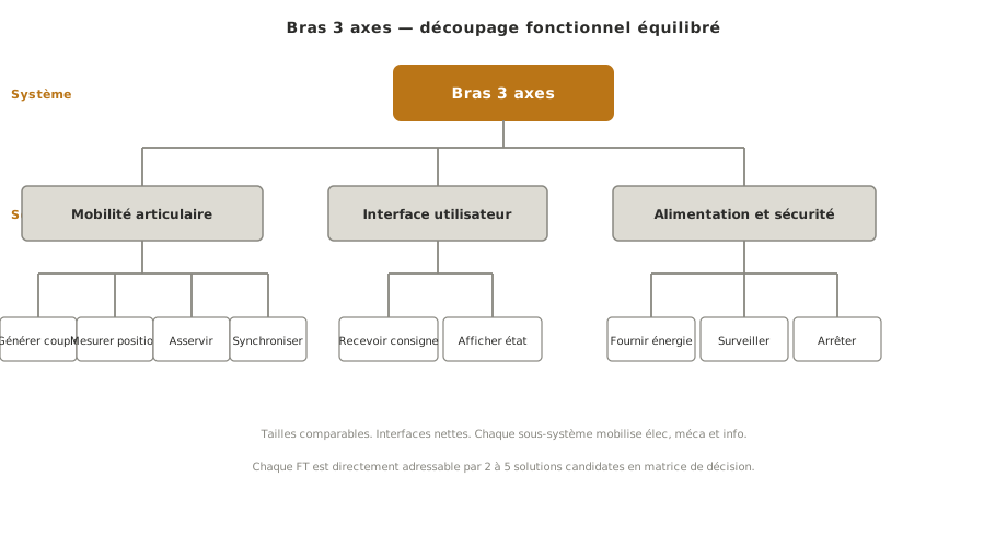
The three diagrams are in French, like every diagram in this wiki. In the last one, mobilité articulaire is joint mobility, interface utilisateur is user interface and alimentation et sécurité is power and safety.
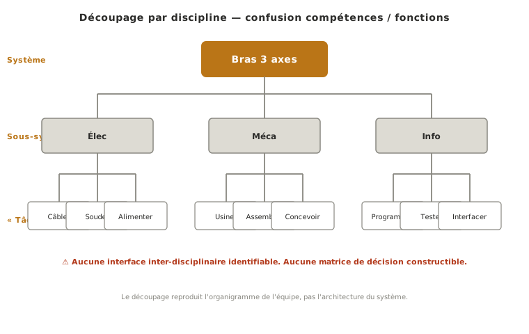
Poor
Why it is poor. The split by discipline (Élec / Méca / Info) reproduces the org chart of the team, not the architecture of the system. It says who works on what, not how the system is organised. The interfaces cannot be defined: the “Élec” branch carries no technical function as long as nobody knows which subsystem it powers. Worse, this split blocks what comes next: there is no way to build a decision matrix on “the electronics part”. The matrix works by technical function, not by discipline.
What the mistake actually cost. On this project the team worked six weeks in disciplinary silos, believing it was following the method. When the time came to set the disciplinary solutions against each other, nobody had defined where the boundary ran between the microcontroller (software) and its power supply (electronics), nor who specified the gears on the mechanics and electronics side. Three extra weeks to break the system down properly and redo the step 2 decisions.
Fair
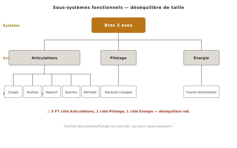
Why it is only fair. The subsystems are properly functional (Articulations, Pilotage, Énergie, that is joints, control and power) and each of them draws on several disciplines, which is already a clear step up from the disciplinary version. But the split still suffers from two weaknesses. Size imbalance: Articulations concentrates most of the technical substance (generating torque, measuring position, running the control loop, synchronising the three axes), while Énergie comes down to “supply the power”. Interfaces described incompletely: the boundary between Articulations and Pilotage is not settled. The control loop runs across both blocks, and which of them owns it? As long as the boundary is not spelled out, two students working in parallel on these two subsystems cannot make progress independently.
Good
Why it is good. The split into joint mobility / user interface / power and safety meets the three criteria of a good split. Comparable sizes: each subsystem carries 3 to 4 internal technical functions of similar effort. Clean interfaces: joint mobility receives a position instruction from user interface and regulated power from power and safety, and returns a measured position. Each of them draws on electronics, mechanics and software. There is no single-discipline block. The technical functions can each be addressed directly by a candidate solution: “generate torque on each axis” calls for 2 to 5 candidates (servomotor, stepper motor, DC motor plus gearbox and so on) to be set against each other in a decision matrix. The split leads straight into step 2 of concept.
Pitfalls
Splitting by discipline. The most common trap on a school project: reproducing the skills of the team (mechanics / electronics / software) instead of the function of the system. Reword the blocks as functions of the system (“put into movement”, “regulate the energy”). Each of them will draw on several disciplines, which is exactly what is expected of a mechatronics subsystem.
Jumping straight to components. Writing “stepper motor” or “ESP32” in the tree is a mistake about the level of abstraction. At this stage neither the solutions nor the components are decided. What is identified is which functions have to be delivered. The components come in the technical design file, once a decision matrix has settled the choice.
Confusing a service function with a technical function. Rewriting the FP and FS of the CdCF (main function and secondary function) into the tree amounts to having broken nothing down. Quick test: does this function face outwards (a service delivered) or inwards (internal delivery)? If it could appear in the pieuvre, it is a service function. The breakdown has to produce something else.
Going too deep. A tree with 5 or 6 levels is generally a sign that the technical design file has been anticipated. If the last leaf looks like a specific sub-component (“choose the filtering capacitor”), the target has been overshot. Go back up to a level where the leaf reads “filter the supply voltage”, addressable but not locked onto one solution.
Tolerating a size imbalance. A subsystem that concentrates most of the technical substance deserves to be divided. The imbalance is a signal to reread, not a fate: either the block was defined too broadly, or the others were not broken down far enough. Either way, go back over it.
Breaking the system down once and freezing it. The split changes as the solutions get explored. A technical function that looked isolated can turn out to be needed by two subsystems. Two distinct functions can share the same candidate solution. Go back over the breakdown at each discovery, rather than piling up patches in the margin.
Special case — redesign and reverse engineering
When the project is a redesign of an existing system (reworking a school demonstrator, updating an internal product) or a functional analysis starting from an object already built (teaching reverse engineering), the breakdown runs the other way: you start from the observable hardware and work back up to the technical functions it delivers, then to the service functions it renders.
The exercise is still useful, with two precautions:
- Do not confuse observable components with technical functions. A servomotor visible in the object does not make the breakdown: it delivers a technical function that has to be named explicitly (“generate torque on the axis”). Going through the verb plus complement wording stays mandatory, even when the component is right there.
- Compare the breakdown obtained with the target CdCF. If the project is a redesign, the target CdCF can differ from the CdCF of the original object. The functional breakdown of what exists then serves as a starting point, not as a reference to copy exactly. Settling the deviations is precisely what the new concept phase has to do.
Where it fits in the project
- Step 1 of the concept phase — the main phase where the breakdown is produced, straight out of the CdCF
- Step 2 of the concept phase — each leaf technical function calls for its own decision matrix setting 2 to 5 candidate solutions against each other
- Technical design file — the split into subsystems often structures the chapters of the file (one subsystem, one design section)
A careful split at step 1 of concept saves you from revising it at every later step, where the cost of reworking grows with the progress of the project.
See also
- Concept — the phase the functional breakdown sits in (step 1)
- Cahier des charges fonctionnel — the upstream input, source of the service functions to deliver
- Function — the FP/FS/FC typology whose service functions are the roots of the breakdown
- FAST — a deeper formalisation of one branch of the breakdown through a WHY / HOW logical chain
- Functional block diagram — the downstream view on the electronics and software side, turning the technical functions into hardware blocks and flows
- Decision matrix — the downstream tool that settles between candidate solutions for each technical function