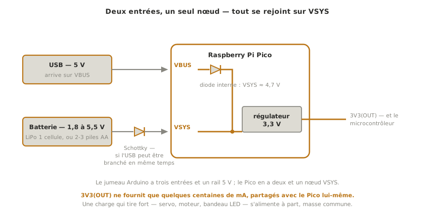
Powering a Pico means giving it the voltage and the current it needs to start, run its program, and feed the external components. The layout differs from an Arduino: no barrel jack and no 7805 linear regulator, but three key pins — VBUS (5 V from USB), VSYS (system input, 1.8–5.5 V) and 3V3(OUT) (regulated 3.3 V output) — around a buck-boost regulator that makes the internal 3.3 V. Picking the right path — and sizing it — is the first thing to check when a project reboots on its own or refuses to start.
What is it for?
As long as a project sits on a breadboard powered over USB, all is well. As soon as motors, relays, wireless modules or a display come in, the current climbs, and the Pico’s 3.3 V output quickly reaches its limits. Knowing the power paths lets you pick the right source, separate the supplies when actuators disturb the logic, and anticipate the peaks (Wi-Fi transmitting, a motor starting).
Step by step
Four steps: pick the path, estimate the current, wire it, check stability.
1. Pick the power path
| Pin | Role | Range | Use |
|---|---|---|---|
| VBUS (pin 40) | 5 V coming from USB | 5 V (if USB is plugged in) | pass the USB 5 V on to a 5 V module |
| VSYS (pin 39) | system input (to the internal regulator) | 1.8 – 5.5 V | power the Pico from a battery or an external source |
| 3V3(OUT) (pin 36) | regulated 3.3 V output | 3.3 V, limited current | power 3.3 V sensors and modules (light loads) |
| 3V3_EN (pin 37) | enables the 3.3 V regulator | tied to GND = off | a software power switch |
Basic rule: USB as long as it is enough; otherwise VSYS (1.8–5.5 V) for an external source or a battery. The 3V3(OUT) pin is an output, not an input. You do not inject a voltage into it.
2. Estimate the total current
Add up the consumptions, estimated on the high side:
- Pico alone: about 25–40 mA.
- Simple sensors (DHT11, HC-SR04): 1–15 mA each.
- SG90 servo: 10 mA at rest, 100–200 mA while moving, up to 500 mA when stalled.
- Relay module: 70–80 mA when it pulls in.
- DC motor: 100 mA to several amps.
- Wi-Fi (Pico 2 W) transmitting: peaks of several hundred mA.
- WS2812 LED strip: 3–5 A at full white — a dedicated supply is mandatory.
The 3V3(OUT) output only delivers a few hundred mA (shared with the Pico itself): do not hang a heavy load on it. Beyond that, power the load separately (from VBUS/5 V or from a dedicated supply). For the general sizing method (power budget, margins), see designing a power supply.
3. Wire it
USB: a data cable. It brings 5 V onto VBUS, which feeds VSYS through a diode (VSYS ≈ 4.7 V), and the regulator then makes the 3.3 V.
Battery or external source: connect the source (1.8–5.5 V) to VSYS and its ground to GND. A single LiPo cell (3.0–4.2 V) or a pack of 2–3 AA cells (3–4.5 V) fall straight inside the VSYS range. If USB may also be plugged in at the same time, feed VSYS through a Schottky diode (the higher source wins, with no conflict) — see the “Powering Pico” note in the datasheet.
5 V module: power it from VBUS (5 V, USB present), share GND, and shift its output signals down for the Pico (logic levels).
4. Check stability
With a multimeter: 3V3(OUT) should read about 3.3 V (3.2–3.4 V). Under load (with an actuator running), it must not sag. The typical symptom of a weak supply: the Pico reboots as soon as an actuator kicks in (the current peak pulls the voltage below the threshold — brown-out — and the board resets, then starts again).
Example — A battery-powered project: Pico plus 3 modules
Estimate: Pico 30 mA + DHT11 2.5 mA + OLED 20 mA + servo 200 mA peak ≈ 250 mA at peak.
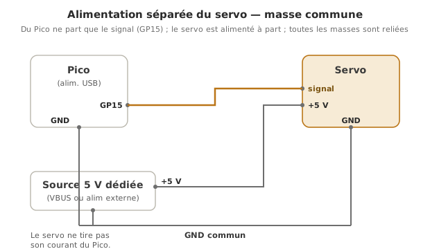
Choice: a single-cell LiPo battery (3.0–4.2 V) on VSYS; DHT11 and OLED powered from 3V3(OUT) (≤ 30 mA each, fine); servo powered separately (its peak would pull the 3.3 V down).
from machine import Pin, PWM
servo = PWM(Pin(15)); servo.freq(50)   # servo on GP15, 50 Hz
# ... read sensors, drive the OLED, drive the servo
On the first attempt, powering the servo from 3V3(OUT) as well makes the Pico reboot whenever it moves. Fix: power the servo from a dedicated 5 V source (or from VBUS if USB is present), with GND shared with the Pico. See servo for good practice on servo supplies.
Pitfalls
Injecting a voltage into 3V3(OUT). It is an output: applying a voltage to it can damage the regulator. To power the Pico externally, go through VSYS.
Going above 5.5 V on VSYS. The VSYS range is 1.8–5.5 V. Applying 7–12 V (the “Arduino jack” reflex) destroys the board. There is no 7805-style input regulator here.
A PC’s USB port for actuators. A reboot when an actuator kicks in is a diagnosis to make before hunting for a software bug. Fix: an external supply.
A hungry load on 3V3(OUT). That output is limited (a few hundred mA, shared with the Pico). A heavy load pulls it down, hence a brown-out. Power the load separately.
An unanticipated Wi-Fi transmit peak (Pico 2 W). Short peaks, invisible on a multimeter. A decoupling capacitor near the supply absorbs the peak and steadies things.
No shared GND. With two supplies (Pico plus load), GND has to be shared, otherwise the signals have no common reference and the system does not work.
Special case — Batteries for standalone projects
- 2–3 AA cells (3–4.5 V) → straight onto VSYS, available anywhere and replaceable without a tool;
- a single-cell LiPo (3.0–4.2 V) → straight onto VSYS, but it needs a dedicated charger and some care (over-discharge);
- to save power on a battery during long idle periods, see deep sleep and deep sleep on MicroPython.
Where it fits in the project
- Step 4 of the concept phase — power is one of the deciding criteria (USB versus standalone, a plugged-in demo versus a mobile one).
- Step 2 of the proof of concept phase — at the first power actuator, estimate the consumption and resize.
- Step 4 of the technical design file phase — the final supply for the demonstrator (with margin) is part of the BOM.
- Step 2 of the integration and testing phase — check that the 3.3 V holds up under load on the integrated system.
Power is the most underestimated part of a beginner’s project — ignored while all goes well, blamed wrongly when some other bug shows up. Measuring it with a multimeter at the first suspicious symptom saves hours of wandering.
See also
- MicroPython — the module hub
- Getting started — where USB power is met first
- Deep sleep — cutting consumption for battery life
- Expansion board — the plug-on board that pushes consumption up
- Logic levels — 3.3 and 5 V living together
- Designing a power supply — the cross-cutting principles applied here
- Reading a datasheet — finding the nominal currents of the components
- Powering an Arduino board — the equivalent (USB / jack / Vin)