STM32CubeMX is the graphical configuration tool for STM32 microcontrollers: you assign the pins, set the clock tree, tune the peripherals, and CubeMX then generates the matching initialisation code. It is the heart of the STM32’s native door, and the family’s most distinctive contribution: you do not program first, you configure the microcontroller: the code comes afterwards. CubeMX can be used on its own or embedded in STM32CubeIDE (the .ioc view met while getting started). The API that this code uses is covered in the HAL.
What is it for?
An STM32 has dozens of pins, several clocks, and peripherals with a great many settings. Writing the whole initialisation by hand (which bits in which registers, in which order) is long and error-prone. CubeMX makes that configuration visual and checked:
- Seeing and resolving conflicts. The graphical pinout shows which functions are available on each pin and flags conflicts (a pin already taken by another peripheral).
- Mastering the clock. The clock tree, the STM32’s emblematic panel, lets you set the frequency of the core and of each bus, computing the dividers and warning about invalid values.
- Generating a sound baseline. The initialisation code produced is consistent with the configuration, and preserves your own code at every regeneration.
CubeMX does not replace an understanding of the hardware: it equips it. Reading the datasheet is still useful in order to know what to configure (see reading a datasheet).
The .ioc file
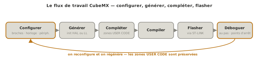
The whole configuration lives in an .ioc file (one per project). It is a text file: it goes into Git just like the code, and two configuration states can be compared. “Generate code” reads the .ioc and writes the initialisation. Changing the configuration and regenerating brings the code up to date without touching what you wrote in the reserved zones.
Configuring the pinout
In the Pinout & Configuration view, every pin of the package is clickable. A click offers its possible functions: GPIO_Output, GPIO_Input, USART2_TX, TIM3_CH1, I2C1_SCL… You assign the functions the project needs. CubeMX colours the pins in use and refuses a conflicting assignment.
On a project created from a Nucleo board, the pinout is already partly filled in (LD2, button, ST-LINK serial port). You start from there and add what you need.
Take a screenshot of the CubeMX Pinout & Configuration view, with a few assigned pins highlighted: LD2 as GPIO_Output, PA2 and PA3 as USART2.
Configuring the clock tree
The Clock Configuration tab shows the clock tree: the source (internal HSI oscillator, or external HSE crystal), the PLL that multiplies the frequency, the SYSCLK system clock, and the prescalers that feed the AHB and APB buses and, through them, the peripherals.
You type the target frequency (often the chip’s maximum) into the SYSCLK box. CubeMX resolves the multipliers and dividers, or flags an impossible combination in red. This is a panel worth understanding: a badly set clock gives wrong speeds everywhere downstream: a UART that does not have the right baud rate, a timer that does not measure the right duration.
Take a screenshot of the CubeMX Clock Configuration tab, showing the HSE to PLL tree, SYSCLK and the AHB and APB prescalers, with the core frequency displayed.
Configuring the peripherals
Every peripheral you enable opens a settings panel: baud rate and format for a UART, prescaler and period for a timer, resolution and channels for an ADC, speed for an SPI bus… Two cross-cutting tabs complete the setup:
- NVIC — to enable the interrupt of a peripheral. Without ticking the matching NVIC line, code in interrupt mode will never be called (a classic trap).
- DMA — to configure a transfer by direct memory access, which offloads the core.
Take a screenshot of the configuration panel of a USART in CubeMX, set to 115200 baud and 8 data bits, with the NVIC Settings tab visible.
HAL or LL, then generate
Before generating, the Project Manager → Advanced Settings → Driver Selector offers an important choice per peripheral: generate the init in HAL (the portable API, the default) or in LL (the low-level layer, closer to the register and lighter). You can mix from one peripheral to the next: HAL for most of them, LL for a peripheral that is critical for performance. (The neighbouring Code Generator tab carries other settings — one file per peripheral, user code preserved — not the choice of driver.)
“Generate Code” then writes main.c, one init file per peripheral, and the MX_<PERIPH>_Init() functions. Everything is marked out with /* USER CODE BEGIN/END */ tags: your code only survives inside those tags.
Example — Configuring an LED and a serial port, then generating
On a Nucleo, let us configure enough to blink and write on the serial port, starting from a board project:
- Pinout —
LD2is already set toGPIO_Output. Check thatUSART2is enabled onPA2/PA3(the ST-LINK serial port on a Nucleo-64). - Clock — leave the board’s default configuration (already close to the maximum).
- USART2 — Baud Rate at
115200, format8N1. - Generate the code.
In main.c, CubeMX has produced MX_GPIO_Init() and MX_USART2_UART_Init(), and declared a huart2 handle. All that is left is to fill in the loop, in the reserved zone:
/* USER CODE BEGIN 3 */
HAL_GPIO_TogglePin(LD2_GPIO_Port, LD2_Pin);            // flips the state of the LED
HAL_UART_Transmit(&huart2, (uint8_t *)"tick\r\n", 6, 100);   // 6 = bytes to send, 100 = timeout in ms
HAL_Delay(1000);                                       // waits one second
/* USER CODE END 3 */
The LED beats out the second, and the serial monitor (115200) shows tick every second. The handle huart2 is the object generated by CubeMX that the HAL functions work on (covered in the HAL). The microcontroller was configured first, and only then was the logic written: that is the whole spirit of the native door.
On a monitor set to 115200:
tick
tick
tick
tick
If the lines scroll too fast or too slowly, it is the clock tree that needs reopening, not the HAL_Delay.
Pitfalls
Code written outside the USER CODE zones. The recurring trap of the native STM32: any code outside the /* USER CODE BEGIN/END */ tags disappears at the next generation. Always write between the tags, and regenerate without fear once the rule is learnt.
Badly set clock tree. A wrong system frequency propagates wrong speeds everywhere: UART at the wrong baud rate, timer at the wrong duration, mistimed waits. Check the source (internal HSI vs external HSE) and read the frequencies computed by CubeMX.
Interrupt enabled in the code but not in the NVIC. Using a peripheral in interrupt mode (HAL_..._IT) without ticking its line in the NVIC tab: the callback is never called, and nothing flags it at build time.
Ignored pin conflict. Assigning a function to a pin while another one already occupies it: CubeMX flags it, do not override.
Wrong chip reference. Creating the project for a variant that differs from the real chip: the pins and peripherals do not match. Starting from the Board Selector for a known board avoids the mistake.
Forgetting to regenerate. Changing the configuration in the .ioc without running “Generate Code” again: the code does not reflect the change.
Exercises
Exercise 1 — The ST-LINK serial port
In CubeMX, which peripheral corresponds to the virtual serial port of a Nucleo-64, and on which pins? What happens if you set its baud rate to 9600 in CubeMX but open the monitor at 115200?
Solution
On most Nucleo-64 boards it is USART2, wired to
PA2(TX) andPA3(RX), connected to the ST-LINK, which exposes it as a virtual serial port over USB. If the configured baud rate (9600) does not match the monitor’s (115200), the characters come out as gibberish: both ends have to share exactly the same rate. This is the direct example of a peripheral setting the whole thing depends on.
Exercise 2 — Adding a timer
You want to blink the LED without a blocking
HAL_Delay, using a hardware timer. In CubeMX, which TIM setting targets a period of 1 s, and which tab must you remember to enable if you intend to use its interrupt?
Solution
You enable a TIMx in Internal Clock, then set its prescaler (Prescaler) and its period (Counter Period) to obtain 1 s: for instance, with a timer clock at 84 MHz, a prescaler of
8400-1brings the counter down to 10 kHz, and a period of10000-1gives one overflow every second. To react to that overflow, you have to tick the timer’s line in the NVIC tab (otherwise theHAL_TIM_PeriodElapsedCallbackcallback will never be called). The detail of the values and of timers is set afterwards. Here, what matters is the prescaler × period pair and enabling the NVIC.
Where it fits in the project
- Step 4 of the proof-of-concept phase. CubeMX is the tool that turns a choice of microcontroller (made during concept) into a software baseline ready to code on. Configuring the clock and the peripherals cleanly at the start of the PoC avoids timing bugs that are hard to diagnose later.
- Traceability. The versioned
.iocfile documents the project’s hardware configuration: a teammate sees at a glance which pins do what, which feeds the technical file.
Understanding that CubeMX configures and that the HAL is the API the generated code uses draws a clear line between the two gestures: you set the microcontroller on one side, you write the logic on the other.
Going further
- Programming with the HAL — the API used by the code CubeMX generates.
- Going down to the register — when the HAL is not enough, or to understand what CubeMX really configures.
- STM32CubeMX page on st.com — documentation, clock trees, examples.
See also
- STM32 — hub of the STM32 tutorials
- Getting started with the STM32 — the
.iocview met for the first time - Programming with the HAL — the API of the generated code, its three modes
- Going down to the register — the layer beneath the HAL
- Timers · ADC · Communication buses — peripherals configured in CubeMX (cross-cutting)