Getting started with the STM32 means installing the official STM32CubeIDE environment, creating a project for your Nucleo board, and uploading a first program through the built-in ST-LINK debugger. Compared to an Arduino, the approach is different: you do not type code straight into an editor, you create a project from your board, which pre-configures the microcontroller automatically. The target program is still Blink (making the user LED flash), the embedded equivalent of “Hello World”. This tutorial takes the native door. For the Arduino door, see programming with the Arduino core.
What is it for?
Getting started validates the whole native chain in one go: editor, configuration generator (CubeMX, built in), GCC compiler, GDB debugger, and ST-LINK link to the board. If one link is broken, Blink does not flash, and you find out straight away, on trivial code, rather than buried inside a complex project.
Beyond the first program, the step has two roles:
Anchoring the native gestures. Creating a board project, generating the code, filling in the reserved zones, building, flashing, stepping through the debugger: these are the gestures repeated in every following STM32 tutorial. Anchoring them once on something trivial frees up attention for the rest.
Discovering the ST-LINK. The USB cable of a Nucleo is not a plain programming cable: it carries flashing, step-by-step debuggingand a virtual serial port. Understanding that triple role from the start saves a lot of confusion.
Step by step
Five steps: install CubeIDE, create a board project, write the blink, build, upload and observe.
1. Install STM32CubeIDE
Download STM32CubeIDE from the ST website (st.com, development tools section). The download requires a free myST account. The tool is free to use and all in one: it bundles the editor, CubeMX, the GCC toolchain for ARM and the debugger.
On Windows, the ST-LINK driver is installed along with the IDE. On Linux, add the udev rules supplied by ST so that the ST-LINK can be reached without sudo.
Take a screenshot of the STM32CubeIDE download page on st.com, with the Windows, Linux and macOS links.
2. Create a project from the board
This is the step specific to the native STM32 flow: you start from the board, not from an empty file. File → New → STM32 Project, then the Board Selector tab. Look for your Nucleo (for example NUCLEO-F411RE or NUCLEO-G431RB), select it, Next, and name the project.
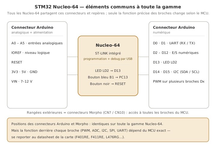
To the question “Initialize all peripherals with their default Mode?”, answer Yes: CubeMX then configures the microcontroller for this board automatically, in particular the user LED LD2 (on PA5, that is D13 on the Arduino connector, on most Nucleo-64 boards) already declared as an output, and the system clock set up.
These landmarks — LED LD2, button B1, connectors — are common to the whole Nucleo-64 range:
Take a screenshot of the Board Selector tab of STM32CubeIDE, with the NUCLEO-F411RE board selected and the Next button visible.
The IDE opens the .ioc configuration view (the pinout of the board) and generates a project skeleton. We will come back to that view in CubeMX. For now, close it, the project is ready.
3. Write the blink — in the right zone
Open Core/Src/main.c. The generated code is marked out with /* USER CODE BEGIN … */ and /* USER CODE END … */ tags. Everything you write between those tags is kept when the configuration is regenerated. Everything written elsewhere is overwritten. That is the golden rule of the native STM32 flow.
Find the main loop while (1) and fill in the USER CODE BEGIN 3 zone:
/* USER CODE BEGIN 3 */HAL_GPIO_TogglePin(LD2_GPIO_Port, LD2_Pin);HAL_Delay(500);/* USER CODE END 3 */
HAL_GPIO_TogglePin flips the state of the pin on every pass. HAL_Delay(500) waits 500 ms. LD2_Pin and LD2_GPIO_Port are the names generated for the LED. There is no need to know the pin number, CubeMX has defined them.
Take a screenshot of the main.c editor in CubeIDE, with the LD2 toggle inserted between the USER CODE BEGIN 3 and USER CODE END 3 markers.
4. Build
Click the hammer icon (Build). The console prints the size of the binary (text, data, bss) and ends with Build Finished. 0 errors. An error here is a code or configuration problem, not a hardware one: the board has not been touched yet.
The console then ends like this:
   text    data     bss     dec     hex  filename
  XXXXX     XXX    XXXX   XXXXX    XXXX  Project.elf

Build Finished. 0 errors
The first three columns are the size summary to note down for your own project: text sits in flash (code and constants), data and bss sit in RAM. This is the only place where you can see whether a binary still fits in the chip.
5. Upload and observe
Plug the Nucleo in through its USB connector on the ST-LINK side (a data cable, not a “charge only” one). Click the green Run arrow: the IDE builds, flashes the binary through the ST-LINK, and starts the program.
Tip
On the first connection, CubeIDE may offer to update the ST-LINK firmware. Accept it: it is quick and it prevents later connection failures. Unlike the ESP32, no button handling is needed: SWD flashing is direct and reliable.
LED LD2 flashes at half-second intervals. The program is running: getting started is validated.
If LD2 stays off, go back over the board selection in the Board Selector (step 2), then see the Pitfalls.
Example — Blink, modified and debugged
To check that you really control what happens, change the delays:
/* USER CODE BEGIN 3 */HAL_GPIO_TogglePin(LD2_GPIO_Port, LD2_Pin);HAL_Delay(100);HAL_GPIO_TogglePin(LD2_GPIO_Port, LD2_Pin);HAL_Delay(900);/* USER CODE END 3 */
The LED now gives a short flash (100 ms) every second. This small step — modify, flash, observe the expected change — is the basic gesture of every following tutorial.
Take the opportunity to discover debugging: click the bug icon (Debug) instead of Run. The program stops at the beginning of main. Set a breakpoint on the HAL_Delay line, step through it (Step Over), and watch the program go round the loop. That is the strength of the ST-LINK: seeing the code run, line by line, which no bare Arduino allows without dedicated hardware.
Take a screenshot of the Debug perspective of CubeIDE, with a breakpoint set inside the while loop and the execution arrow on a line.
Pitfalls
Code written outside the USER CODE zones. This is the number-one pitfall of the native STM32 flow: any code placed outside the /* USER CODE BEGIN/END */ tags disappears at the next CubeMX generation. Always write between the tags.
ST-LINK driver or firmware. Board not detected: check the cable (data, not charge only), accept the ST-LINK firmware update offered by CubeIDE, and on Linux install ST’s udev rules.
Wrong board variant selected. If LD2_Pin is not recognised, or if nothing flashes even though the build passes, it is often because the board picked in the Board Selector does not match yours (the LED is not on the same pin on every Nucleo).
Mistaking the ST-LINK cable for a plain power supply. The USB connector of the Nucleo carries three functions (flashing, debugging, serial port). Plugging the board into a charger powers it but allows neither flashing nor debugging.
Forgetting to launch the right run configuration. On the first Run, CubeIDE sometimes asks you to pick “STM32 C/C++ Application”. Select it. The following times, it is automatic.
Exercises
Exercise 1 — Two rhythms
Change Blink so that the LED stays on for 2 seconds, then flashes quickly three times (100 ms on / 100 ms off), before starting over.
Solution
/* USER CODE BEGIN 3 */HAL_GPIO_WritePin(LD2_GPIO_Port, LD2_Pin, GPIO_PIN_SET);HAL_Delay(2000);HAL_GPIO_WritePin(LD2_GPIO_Port, LD2_Pin, GPIO_PIN_RESET);HAL_Delay(300);for (int i = 0; i < 3; i++) { HAL_GPIO_WritePin(LD2_GPIO_Port, LD2_Pin, GPIO_PIN_SET); HAL_Delay(100); HAL_GPIO_WritePin(LD2_GPIO_Port, LD2_Pin, GPIO_PIN_RESET); HAL_Delay(100);}/* USER CODE END 3 */
You move from Toggle to WritePin to drive the state explicitly (GPIO_PIN_SET / GPIO_PIN_RESET). The for loop factors out the three flashes. That need for rhythms without a blocking HAL_Delay comes back when structuring the firmware.
Exercise 2 — Read the button
Most Nucleo-64 boards have a user button B1 on PC13, already configured as an input by the board project. Turn the LED on as long as the button is pressed, and off otherwise. (Hint: on a Nucleo, B1 is often wired in inverted logic. Pressed = low level.)
Solution
/* USER CODE BEGIN 3 */if (HAL_GPIO_ReadPin(B1_GPIO_Port, B1_Pin) == GPIO_PIN_RESET) { HAL_GPIO_WritePin(LD2_GPIO_Port, LD2_Pin, GPIO_PIN_SET);} else { HAL_GPIO_WritePin(LD2_GPIO_Port, LD2_Pin, GPIO_PIN_RESET);}/* USER CODE END 3 */
HAL_GPIO_ReadPin reads the state of the pin. Button B1 on the Nucleo is tied to ground when pressed (pull-up resistor at rest), so a press corresponds to GPIO_PIN_RESET, hence the inverted test. Pull logic is detailed in the GPIOs.
Special case — STM32duino and PlatformIO
This tutorial uses the native toolchain (CubeIDE), because that is what opens up the real contribution of the STM32. But you can also get started with the board through the Arduino door: STM32duino lets you write a Blink the Arduino way (digitalWrite, delay) in a few lines, with no project and no generation. It is faster for a first contact, at the cost of never seeing the native toolchain. PlatformIO (a VS Code extension) handles both worlds inside the same version-controlled project.
Where it fits in the project
Step 4 of the proof-of-concept phase. The first build and the first flash onto the target board are the founding act of the software PoC. As long as Blink does not flash, no downstream measurement or control loop is credible.
Every downstream STM32 tutorial. Without an effective start, reading the other tutorials without being able to test amounts to reading code without running it. Do the Blink at least once, on the target hardware, as early as possible.
Investing half an hour to validate the complete native chain at the start of the PoC saves hours of hybrid bugs later, when a tooling problem can no longer be told apart from an algorithm problem.