A digital sensor delivers its information coded as a binary signal, as opposed to an analog sensor, which outputs a continuous voltage. The coding varies: a plain logic level (present / absent), a pulse whose width encodes the measurement (ultrasonic), a proprietary 1-wire protocol (DHT11), or an I2C / SPI frame (BMP280, MPU6050). This page covers the first two cases: the I2C and SPI buses have tutorials of their own.
What is it for?
Digital sensors are heavily used measurement blocks: detecting a presence (PIR), measuring a distance (HC-SR04), measuring a rotation speed (Hall effect encoder). Their advantage over analog ones: immunity to cable noise, and a value that is already conditioned. Their downside: you depend on the sensor documentation (protocol, timing, library).
Step by step
First identify the type of signal, then put the method into practice on two proximity sensors: a threshold IR sensor read with a plain Pin.value() (the minimal case), then the ultrasonic HC-SR04, which measures distance through a pulse (wiring, datasheet, code).
1. Identify the type of signal
- Logic level — a
1or0output depending on an event (PIR, inductive presence sensor, magnetic limit switch). Read withPin.value(). - Timed pulse — the width of a pulse encodes the measurement (the HC-SR04 ultrasonic sensor). Read with
machine.time_pulse_us(). - Proprietary protocol — a binary sequence that only a library can decode (DHT11/22 over 1-wire, DS18B20). MicroPython ships the
dhtmodule, for instance. See using a library.
The datasheet always states which of the three families a sensor belongs to.
2. The simplest case — a threshold IR sensor
Before the ultrasonic one, the minimal case: a sensor that outputs 1 or 0 directly, read with a Pin.value(). On the theme of distance, the usual example is the IR obstacle detection board (FC-51 type): it emits an infrared beam and flips its output when an obstacle reflects that beam closer than a threshold set by an on-board potentiometer. Three wires, no timing.
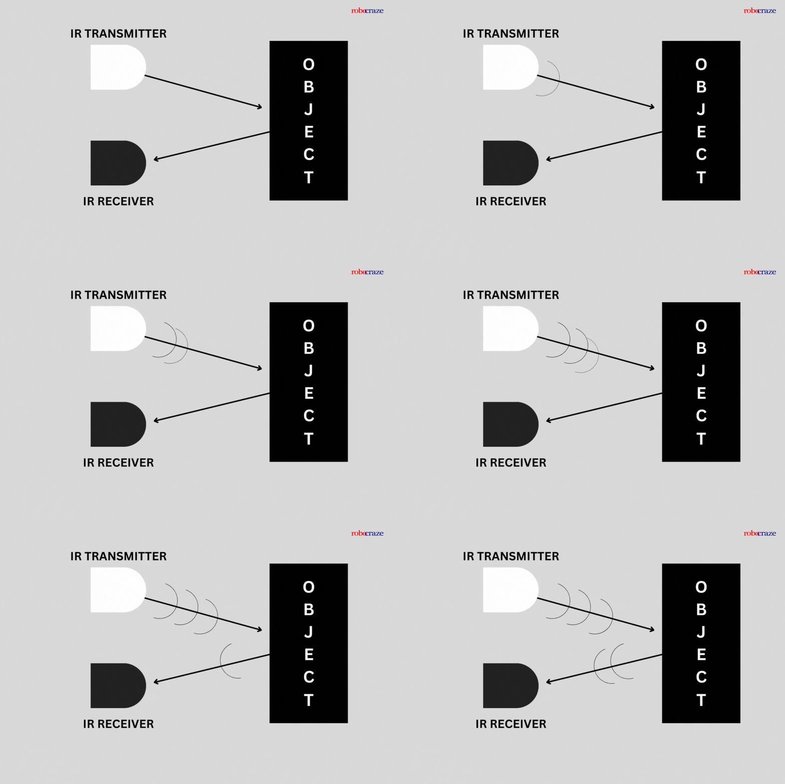
VCC→+5 V(VBUS),GND→GND,OUT→ GP16 (input)
from machine import Pin
from time import sleep

ir  = Pin(16, Pin.IN)
led = Pin(15, Pin.OUT)

while True:
    obstacle = (ir.value() == 0)   # this board: 0 = obstacle detected (active low)
    led.value(obstacle)            # LED lit when an obstacle is close
    print("Obstacle" if obstacle else "Clear")
    sleep(0.2)
The only subtlety is the active level: most of these boards are active low (OUT falls to 0 when an obstacle is detected), hence the == 0 test — to be checked on the product sheet. No debouncing here: unlike a button (a mechanical contact, see reading a digital input), the output is electronic and already clean. This sensor only reports a threshold crossed. To measure the real distance, see the next case.
3. Wire the HC-SR04
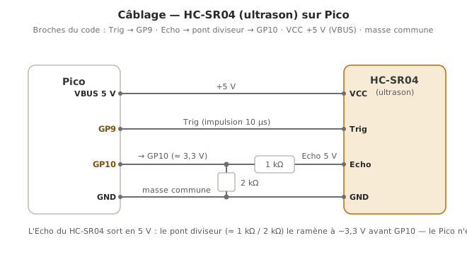
The emblematic sensor of school projects. Careful: its Echo output swings to 5 V, and the Pico is not 5 V tolerant. A voltage divider (or a 3.3 V board) is needed on the Echo line.
VCC→+5 V(VBUS),GND→GND;Trig→ GP9 (output);Echo→ voltage divider → GP10 (input).
4. Read the HC-SR04 datasheet
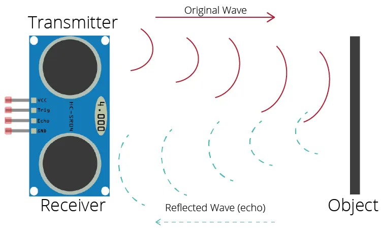
The HC-SR04 works by time of flight: the transmitter sends a burst of ultrasound, the wave bounces off the object, then comes back to the receiver. The round-trip time, given the speed of sound, yields the distance: that is what the Echo pin returns.
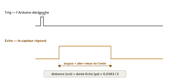
A 10 µs pulse on Trig starts a measurement. Echo returns a pulse proportional to the round trip of the wave. Sound travels at about 343 m/s at 20 °C → distance = duration × 343 / 2. Useful range 2 cm – 4 m.
5. Write the code
time_pulse_us(pin, level, timeout_us) measures the length of a pulse (the equivalent of the Arduino pulseIn) and returns a negative value on timeout.
from machine import Pin, time_pulse_us
from time import sleep, sleep_us

trig = Pin(9, Pin.OUT)            # trigger pin (output)
echo = Pin(10, Pin.IN)           # return echo pin (input)

def mesurer_cm():
    # Trigger: one CLEAN 10 us pulse on Trig
    trig.low()                   # start from a clean low state...
    sleep_us(2)                  # ...settled for 2 us
    trig.high()                  # rising edge: start of the pulse
    sleep_us(10)                 # held for 10 us (the length the sensor expects)
    trig.low()                   # back to rest: pulse emitted
    # Measurement: time_pulse_us waits for the Echo pulse and returns its length (us)
    duree = time_pulse_us(echo, 1, 30000)   # 30 ms timeout; < 0 if no echo
    if duree < 0:
        return -1                # out of range / no echo
    return duree * 0.0343 / 2    # duration -> distance (see the note)

while True:
    d = mesurer_cm()
    print("Out of range" if d < 0 else "{:.1f} cm".format(d))
    sleep(0.1)                   # one reading every 100 ms (~10 Hz)
How to read this code. Two gestures only. Trigger: a clean 10 µs pulse is imposed on Trig. The initial low() (2 µs) guarantees a sharp rising edge, and 10 µs is the length the sensor expects before firing a burst of ultrasound. Measure: time_pulse_us(echo, 1, 30000) puts the program on hold for the pulse on Echo and returns its length in microseconds — the round-trip time of the wave. A negative value means no echo came back before the timeout (30 ms), so the target is out of reach. The × 0.0343 / 2 conversion turns that duration into a distance: 0.0343 cm/µs is the speed of sound, and we divide by two because the wave travels out and back.
Move your hand closer and further away. The distance appears in the REPL:
23.4 cm
18.2 cm
12.1 cm
7.6 cm
Out of range
8.9 cm
One decimal place here, imposed by the "{:.1f}" format: the Arduino twin shows two, simply by default in Serial.print(). And Out of range appears as soon as the hand leaves the cone: that is the negative value returned by time_pulse_us() after the 30 ms.
Example — Threshold detector with a warning LED
from machine import Pin, time_pulse_us
from time import sleep, sleep_us

trig = Pin(9, Pin.OUT)
echo = Pin(10, Pin.IN)
led  = Pin(15, Pin.OUT)
SEUIL_CM = 20

def mesurer_cm():
    trig.low(); sleep_us(2)
    trig.high(); sleep_us(10); trig.low()
    d = time_pulse_us(echo, 1, 30000)
    return -1 if d < 0 else d * 0.0343 / 2

while True:
    d = mesurer_cm()
    if 0 < d < SEUIL_CM:
        led.on()
        print("ALERT:", round(d, 1), "cm")
    else:
        led.off()
    sleep(0.1)
Factoring the reading into the function mesurer_cm() foreshadows how embedded code gets organised (see firmware and debugging a program).
Pitfalls
Confusing digital and analog. A logic-level presence sensor is read with Pin.value(), not through the ADC. Conversely, an LM35 is analog despite its name — see reading an analog sensor.
A 5 V Echo wired straight to the Pico. The HC-SR04 drives Echo at 5 V: with no voltage divider, the pin is damaged (the Pico is not 5 V tolerant). A pitfall specific to 3.3 V boards.
Forgetting the time_pulse_us() timeout. With no timeout, the call can block if no echo comes back. Always pass the third argument (in µs). For 4 m, about 23 ms → 30 ms.
Wild readings. The HC-SR04 sometimes returns nonsense — filter it (a median over 3-5 readings) before feeding a control loop (see filtering measurements).
Measuring too often. The measurement cycle is around 60 ms. Measuring faster gives inconsistent results. 10 Hz is a good rate.
An unsettled PIR. A PIR needs 30–60 s to settle after power-up. Reading during that time gives noise.
Special case — Sensors on an I2C or SPI bus
Many modern sensors (BMP280, MPU6050, VL53L0X) communicate over a bus: digital, but a category treated separately — see I2C and SPI. The wiring and the code differ radically.
Where it fits in the project
- Step 2 of the proof of concept phase — every sensor is validated in isolation before integration: wiring, raw reading, observed range.
- Step 1 of the integration and testing phase — every sensor requalified on its own.
Wiring a sensor, reading its documentation, getting a credible measurement out of it: that is the loop that makes a proof of concept, and it is worth making routine for every sensor in the project.
See also
- MicroPython — the module hub
- Reading an analog sensor in MicroPython — the continuous alternative
- I2C in MicroPython — the bus for more capable sensors
- Using a library — for DHT, DS18B20 and others
- Reading a datasheet — identifying the nature of the signal
- Filtering measurements — smoothing sensor noise
- Reading a digital sensor (Arduino) — the C++ equivalent