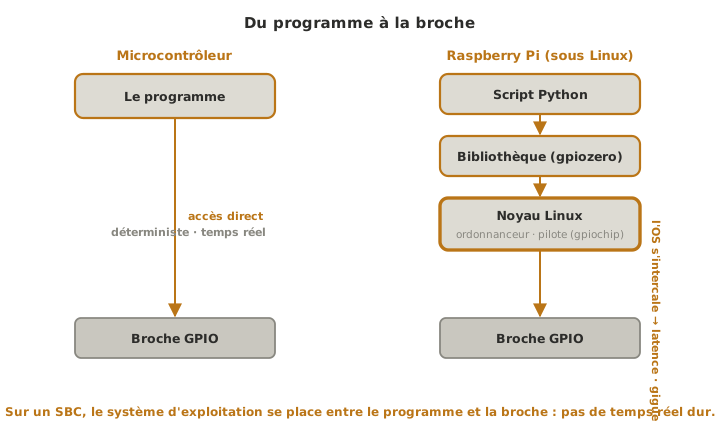
Driving the GPIO from Linux means commanding the Raspberry Pi’s input/output pins from a program, in Python most of the time, while an operating system runs in the background. The principle is still that of any GPIO: an output pin applies a logic level, an input pin reads one. But here the program does not touch the hardware directly: it goes through a library, then through the Linux kernel, before reaching the pin. That extra layer is both a comfort (readable Python code) and a limit (no hard real time).
What is it for?
It is the bridge between the SBC’s software power and the physical world: reading a sensor, lighting an LED, driving a relay or commanding a motor from a program that, elsewhere, does vision or talks to the network. Without GPIO, the Pi stays a computer cut off from the mechatronic system. With it, it becomes a command target in its own right (in the sense of the “programming or configuring a digital controller” criterion).
The libraries
Three Python libraries coexist. Only one is used at a time.
gpiozero— the recommended high-level library. It thinks in objects (LED,Button,Servo,DistanceSensor…) rather than raw pins, which makes the code short and readable. It leans automatically on the right low-level layer for the board (the Pi 5 included).RPi.GPIO— the old historical library, more verbose (you configure each pin by hand). Very present in older tutorials, but it does not work on the Raspberry Pi 5.lgpio— a modern low-level library, Pi 5 compatible, used directly when fine control is needed. It is one of the layersgpiozerocan rest on.
Tip
Start with
gpiozero. You go down tolgpioonly if a precise need calls for it. This is exactly the logic of abstraction layers on a microcontroller: stay high as long as it is enough.
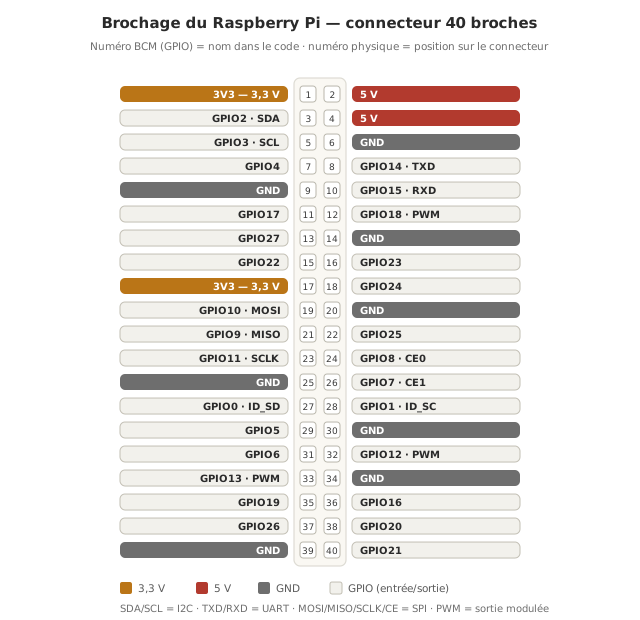
All these libraries designate pins by their “BCM” GPIO number (GPIO17, for instance), which is not the physical position number on the connector. It is a classic source of confusion: a pinout of the Pi’s 40-pin connector is essential to wire correctly.
Lighting an LED
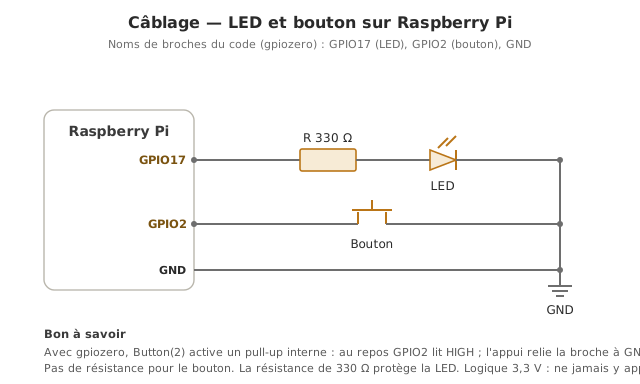
Wiring: the GPIO17 pin → a resistor (~330 Ω) → the LED’s anode → the cathode → a GND pin. The resistor limits the current. The output level is at 3.3 V.
With gpiozero, the program fits in a few lines:
from gpiozero import LED
from time import sleep

led = LED(17)        # GPIO17 (BCM numbering)

while True:
    led.on()
    sleep(0.5)
    led.off()
    sleep(0.5)
LED(17) creates the object, on() / off() drive its state. The library even offers a shortcut for blinking: led.blink(on_time=0.5, off_time=0.5) does the same thing in the background, with no blocking loop.
Warning
The current a Pi pin can supply is limited (on the order of a few milliamperes to ~16 mA per pin, with a total not to be exceeded across the whole connector). You never connect a motor or a power actuator directly to a pin: it needs a transistor, an H-bridge or a relay, just as on a microcontroller. An LED with its resistor is within bounds. Beyond that, you go through a power stage.
Reading a button
Wiring: a button between GPIO2 and GND. Enable the internal pull-up resistor: at rest the pin reads a high level, when pressed it is pulled to ground (low level). gpiozero handles that pull-up by default.
from gpiozero import LED, Button
from time import sleep

bouton = Button(2)   # GPIO2, internal pull-up (pressed = low level)
led = LED(17)

while True:
    if bouton.is_pressed:
        led.on()
    else:
        led.off()
    sleep(0.01)
Button exposes is_pressed, but also an event-based approach, which is more idiomatic:
from gpiozero import Button
from signal import pause

bouton = Button(2)
bouton.when_pressed  = lambda: print("Appui")
bouton.when_released = lambda: print("Relâché")

pause()   # keeps the program alive, waiting for events
This is the equivalent, on the SBC side, of reading a logic input on a microcontroller, in a more compact form: debouncing and event handling are already in the library.
No hard real time
Here is the deep difference with a microcontroller, and it conditions what can be entrusted to the Pi. Between the script and the pin, the Linux kernel sits in the way: its scheduler can suspend the program at any moment to run another task. Consequences:
- the duration of a
sleep()is not guaranteed to the millisecond: it can stretch if the system is busy; - the jitter (variation in reaction time) makes the Pi unsuited to a finely timed control loop;
- software PWM (
PWMLED, for instance) trembles: for a clean signal, hardware PWM is needed, and even that stays less reliable than a microcontroller timer.
The practical rule: the SBC for the high level (decision, vision, network), the microcontroller for real time (control loops, timed motor commands). When a project needs both, you make them work together (see the SBC on a project).
Logic levels — 3.3 V
The Pi’s pins are at 3.3 V and do not tolerate 5 V. Reading the output of a sensor powered at 5 V, or an Arduino pin, directly on a Pi input can damage the pin. The remedy: a level shifter between the 5 V and the Pi. The detail is in logic levels.
Pitfalls
Confusing the BCM number with the physical number. LED(17) targets GPIO17, not the 17th pin of the connector. Always wire with a pinout in front of you.
Applying 5 V to an input. The GPIO is not 5 V tolerant. A 5 V signal goes through a level shifter, never straight in.
Drawing too much current from a pin. An LED with a resistor, yes; a motor, no. Beyond a few milliamperes, a power stage is mandatory.
Expecting real time. Fast regulation or a signal timed to the microsecond cannot be done reliably under Linux. If the project calls for it, move that part onto a microcontroller.
Using RPi.GPIO on a Pi 5. The old library does not work there. Prefer gpiozero (which adapts) or lgpio.
Going further
- gpiozero documentation — recipes for LEDs, buttons, sensors, motors.
- Raspberry Pi GPIO pinout — the 40-pin connector, BCM numbers and functions.
See also
- Raspberry Pi — hub of the SBC module
- The SBC on a mechatronics project — splitting high level (SBC) and real time (microcontroller)
- GPIO — the notion of a logic input/output, independent of the board
- Logic levels — 3.3 V logic and adapting from 5 V
- O — reading an input, driving an output