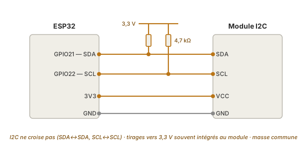
I2C is the two-wire bus (SDA for the data, SCL for the clock) that links several peripherals — sensors, OLED displays, real-time clocks — to the ESP32, each one identified by an address. On the ESP32 it is driven with the Wire library. Its default pins are GPIO21 (SDA) and GPIO22 (SCL), but they are remappable, and the chip has two controllers (Wire and Wire1).
What is it for?
A single pair of wires is enough to question a whole cluster of components:
Reading sensors. Temperature, pressure, humidity, accelerometer: most digital sensors speak I2C, each with its own library.
Displaying. Small OLED screens (SSD1306) and LCDs on an I2C backpack are addressed over two wires, without tying up a dozen pins.
Chaining several modules. As long as their addresses differ, sensors and display share the same SDA/SCL bus.
How the protocol works (addressing, ACK, controller/target) is described in the cross-cutting concept page I2C. Here you see how to wire it and code it on the ESP32.
Step by step
Four moves: wire it, initialise, scan the addresses, use a library.
1. Wire it: two wires, two pull-up resistors
SDA and SCL are open-drain lines: they need pull-up resistors (~4.7 kΩ) to 3.3 V to come back up to the high state. Most modules already carry them: no need to add any if a single module is present.
Warning
Pull up to 3.3 V, not to 5 V. The SDA/SCL lines of a module powered at 5 V come back up to 5 V and can damage the pins of the ESP32. Power the module at 3.3 V, or insert a level shifter (see logic levels).
2. Initialise the bus
Wire.begin() with no argument uses the default pins (GPIO21/22). For other pins, you pass them explicitly:
#include <Wire.h>const int SDA_PIN = 21;const int SCL_PIN = 22;void setup() { Wire.begin(SDA_PIN, SCL_PIN); // same as Wire.begin() here (default pins)}
3. Scan the addresses
Before using a module, you check that it answers, and at which address. The scanner questions every possible address and notes the ones that acknowledge (endTransmission() returns 0).
This scanner is diagnostic tool number one of the I2C: a silent bus (no address found) almost always betrays a wiring or pull-up problem.
4. Use a library
Once the address is known, you install the library of the component (Adafruit, Sparkfun…), which hides the raw exchanges. You almost never handle Wire.write() / Wire.read() by hand.
Example — Scanning the bus and reading the addresses
A concrete case: list in the monitor every peripheral present on the bus. You wire one or more modules, upload, and read the addresses found.
#include <Wire.h>const int SDA_PIN = 21;const int SCL_PIN = 22;void setup() { Serial.begin(115200); Wire.begin(SDA_PIN, SCL_PIN); Serial.println("Scanning the I2C bus...");}void loop() { int trouves = 0; for (byte adr = 1; adr < 127; adr++) { // 7-bit addresses: 1 to 126 Wire.beginTransmission(adr); if (Wire.endTransmission() == 0) { // 0 = a module acknowledged (ACK) Serial.print(" module at address 0x"); if (adr < 16) Serial.print("0"); // print on 2 digits Serial.println(adr, HEX); trouves++; } } if (trouves == 0) { Serial.println(" no module - check wiring and pull-ups"); } delay(3000);}
endTransmission() returns 0 when a target answers at the address tried: that is the acknowledge (ACK) of the protocol. You sweep from 1 to 126 (the 7-bit addresses) and print the ones that answer in hexadecimal. An SSD1306 shows up at 0x3C, a BME280 at 0x76…
With an SSD1306 display and a BME280 sensor on the bus, the monitor prints:
Scanning the I2C bus...
  module at address 0x3C
  module at address 0x76
  module at address 0x3C
  module at address 0x76
The list repeats every 3 seconds: unplugging a module mid-scan makes it disappear from the next sweep.
Pitfalls
No pull-up resistors. Pitfall number one: the scanner finds nothing. Without a pull-up to 3.3 V, SDA/SCL stay stuck low and the bus is mute. A module with built-in pull-ups is enough. Otherwise, add two ~4.7 kΩ resistors.
Powering at 5 V. The lines then come back up to 5 V on 3.3 V pins: risk of destruction. Power the module at 3.3 V.
Two modules at the same address. They answer at the same time and jam each other. The fix: an address jumper on one of them, or the second bus Wire1 (see Special case).
SDA and SCL swapped. Nothing answers. Check that SDA goes to GPIO21 and SCL to GPIO22 (or the declared pins).
Ground not tied. Like every bus, the I2C needs a common ground between the ESP32 and the modules.
Wires too long at 400 kHz. The capacitance of the wires distorts the edges. On a long link, drop back to 100 kHz (Wire.setClock(100000)).
Exercises
Exercise 1 — Printing on an OLED display
Wire an SSD1306 OLED display (I2C) and print “Bonjour ESP32”. The usual address is 0x3C. Hint: use a library (Adafruit SSD1306 + GFX).
Answer to exercise 1
The library handles the I2C exchanges. You initialise the display at its address, write, and refresh with display().
#include <Wire.h>#include <Adafruit_GFX.h>#include <Adafruit_SSD1306.h>Adafruit_SSD1306 ecran(128, 64, &Wire);void setup() { Wire.begin(21, 22); ecran.begin(SSD1306_SWITCHCAPVCC, 0x3C); // address found by the scan ecran.clearDisplay(); ecran.setTextSize(1); ecran.setTextColor(SSD1306_WHITE); ecran.setCursor(0, 0); ecran.println("Bonjour ESP32"); ecran.display(); // required: sends the buffer to the display}void loop() {}
display() is essential: until you call it, the text stays in the buffer and the screen shows nothing.
Exercise 2 — Two sensors at the same address
You have two identical sensors (so the same address), which you cannot change. How do you read both on the same ESP32?
Answer to exercise 2
You spread the two sensors over the two buses of the ESP32: Wire on GPIO21/22, Wire1 on two other pins.
#include <Wire.h>TwoWire I2Cbus2 = TwoWire(1); // second controllervoid setup() { Serial.begin(115200); Wire.begin(21, 22); // sensor A I2Cbus2.begin(25, 26); // sensor B, same address, other bus}
The two I2C controllers of the ESP32 are independent: two modules at the same address live side by side on distinct pins.
Special case — The second bus and the speed
The ESP32 has two I2C controllers. The first is Wire. The second is instantiated through TwoWire(1) (often named Wire1), on the pins of your choice. Useful to separate two modules at the same address, or to isolate a slow sensor from a fast bus.
The speed is set with Wire.setClock(100000) (standard, 100 kHz) or 400000 (fast, 400 kHz). The fast mode suits short links. On long wires, stay at 100 kHz.
On the C3 / S3 variants, the default pins differ from GPIO21/22. Check the pinout through configuring the GPIO and pass them to Wire.begin(sda, scl).
Where it fits in the project
Proof of concept — an I2C sensor (BME280, MPU6050) validates a measurement with no interface electronics. The scanner confirms the wiring in a minute.
Integration and testing — several modules on a single bus cut the wiring of the embedded subsystem. The I2C display shows the state live during the trials.