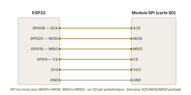
SPI is the synchronous, fast serial bus that links the ESP32 to demanding peripherals — SD card, TFT display, high-rate sensors — over four wires: SCK (clock), MOSI (outgoing data), MISO (incoming data) and one CS per peripheral. On the ESP32, two buses are usable (VSPI and HSPI). The default VSPI pins are SCK = GPIO18, MISO = GPIO19, MOSI = GPIO23, CS = GPIO5, and they are remappable, at the price of a capped speed once you leave the native pins.
What is it for?
Where the I2C tops out, the SPI transfers fast and in full duplex (sending and receiving at the same time):
Storing. A microSD card records measurements and logs. That is the most common use of the SPI in a project.
Displaying richly. Colour TFT screens refresh whole images — out of reach over I2C.
Reading fast. Some ADCs, motion sensors and radio modules exist only in SPI, for the throughput.
How the protocol works (clock, full duplex, selection by CS) is described in the cross-cutting concept page SPI. Here you see how to wire it and code it on the ESP32.
Step by step
Four moves: wire the harness, initialise, use a library, add peripherals.
1. Wire it: a shared harness, one CS per module
SCK, MOSI and MISO are common to every peripheral on the bus. Only the CS (Chip Select) belongs to each one: it is what designates the active module. Unlike the UART, the SPI does not cross over: MOSI goes to MOSI, MISO to MISO.
Warning
A 3.3 V peripheral. The ESP32 works at 3.3 V: a 5 V SPI module (some SD readers with a regulator) must either carry a built-in level shifter, or go through an adapter (see logic levels).
2. Initialise the bus
SPI.begin() with no argument uses VSPI (default pins). The libraries (SD, TFT) often call begin() themselves. What you mainly pass them is the CS:
#include <SPI.h>const int CS = 5; // VSPI: SCK=18, MOSI=23, MISO=19 by default
3. Use a library
You rarely handle SPI.transfer() by hand: a library (SD, Adafruit GFX for a TFT) takes care of the protocol. You give it the CS and, if needed, a clock speed.
4. Add peripherals
For a second module, you share SCK/MOSI/MISO and give it another CS (a free GPIO). The code activates a single CS at a time.
Example — Logging to a microSD card
A concrete case: write a line of measurement into a file on the SD card, then read it back. This is the entry point of the embedded datalogger.
#include <SPI.h>#include <SD.h>const int CS = 5; // CS of the SD reader on GPIO5 (VSPI)void setup() { Serial.begin(115200); if (!SD.begin(CS)) { // VSPI by default: SCK18 / MISO19 / MOSI23 Serial.println("SD card missing or miswired"); return; } File f = SD.open("/mesures.csv", FILE_WRITE); // opens (creates if needed) if (f) { f.println("time;value"); // header f.println("0;512"); // one measurement f.close(); // close() required: flushes the buffer to the card Serial.println("Written."); } // reading back f = SD.open("/mesures.csv"); while (f && f.available()) { Serial.write(f.read()); // sends the content back to the monitor } f.close();}void loop() {}
SD.begin(CS) initialises the VSPI bus and mounts the card. SD.open(..., FILE_WRITE) opens the file for writing. The close() is essential: it flushes the buffer and closes the file, without which the last write can be lost. Reading back reopens the file and sends its content to the monitor.
In the monitor:
Written.
time;value
0;512
The last two lines do not come from a println of the sketch: they are the content of the file, read back byte by byte and sent by Serial.write(). The proof that the write did reach the card.
Pitfalls
MOSI and MISO crossed over. A reflex inherited from the UART, but the SPI does not cross over: MOSI on MOSI, MISO on MISO. Crossing them gives a silent module.
CS forgotten or shared. Two modules on the same CS answer together and jam each other. Every peripheral has its own CS on a distinct GPIO.
SD card not detected. Often a wrong CS, a swapped MISO/MOSI wire, or a badly formatted card (FAT32). Check the wiring pin by pin against the code first.
A 5 V peripheral on the ESP32. Lines at 5 V attack the 3.3 V pins. Pick a 3.3 V module or shift the level.
Remapped pins, throughput down. Going through GPIOs other than the native pins routes the signal through the internal matrix: the speed drops (~40 MHz instead of 80). For maximum performance, keep the default VSPI pins.
Ground not tied. Like every bus, the SPI demands a common ground between the ESP32 and the peripheral.
Exercises
Exercise 1 — A clocked datalogger
Take the SD card again and record a measurement every second, without freezing the program. Hint: clock on millis(), open/write/close on every reading.
Answer to exercise 1
You open in append mode, write a line, close again, on a non-blocking cadence.
#include <SPI.h>#include <SD.h>const int CS = 5;const int CAPTEUR = 34; // ADC1unsigned long dernier = 0;void setup() { Serial.begin(115200); SD.begin(CS);}void loop() { if (millis() - dernier >= 1000) { // every second, without delay() dernier = millis(); File f = SD.open("/log.csv", FILE_APPEND); // appends at the end if (f) { f.print(millis()); f.print(";"); f.println(analogRead(CAPTEUR)); f.close(); // closes on every line: nothing is lost } }}
FILE_APPEND writes on after the rest without erasing. Closing after every line guarantees that the data is on the card even if the power drops.
Exercise 2 — Two peripherals on the bus
Add a second SPI module (a display, say) beside the SD card. What do they share, and what tells them apart?
Answer to exercise 2
They share SCK/MOSI/MISO. Each has its own CS on a distinct GPIO.
const int CS_SD = 5; // SD cardconst int CS_TFT = 15; // display, other CSvoid setup() { pinMode(CS_SD, OUTPUT); pinMode(CS_TFT, OUTPUT); digitalWrite(CS_SD, HIGH); // at rest, both CS are high (inactive) digitalWrite(CS_TFT, HIGH); SPI.begin(); // shared VSPI harness // each library activates its own CS for the length of its exchange}
The harness (SCK/MOSI/MISO) is common. It is the CS, active low, that designates the module listening at a given moment.
Special case — The second bus and the speed
The ESP32 offers a second SPI bus, HSPI, to separate two groups of peripherals or to avoid saturation. You instantiate it through SPIClass:
The clock speed is set through SPISettings (often carried by the library). The native pins (VSPI: 18/19/23/5; HSPI: 14/12/13/15) allow up to 80 MHz. Remapped pins top out lower.
On the C3 / S3 variants, the organisation of the SPI buses and the default pins differ. Refer to the pinout through configuring the GPIO.
Where it fits in the project
Proof of concept — as soon as measurements have to be stored (datalogger) or richly displayed, the SPI is the right bus. The SD card example validates the recording in a few lines.
Integration and testing — logging to SD during the trials gives a trace you can exploit afterwards. The TFT display shows the state of the system on its own.