A kinematic diagram is a simplified drawing of a mechanism showing only its joints between parts and the motions those joints allow — not the shapes, not the dimensions. It is the tool for describing the mechanical architecture of a system and counting its degrees of freedom before drawing a single part. This page covers what it is and how to read one in a project. The full theory (the catalogue of joints, screw theory, mobility calculation) belongs to the mechanics course.
What is it for?
In the concept phase, once the functions have been laid down (see the functional block diagram), you have to describe how the parts move relative to one another. The kinematic diagram answers three questions:
- How many independent motions? The number of degrees of freedom (DOF) — an arm that has to reach a point in space needs at least three.
- Which mechanical architecture? A series of joints (an articulated arm) or a closed structure (an XY table, a platform).
- Is the mechanism as mobile as intended, neither jammed nor unstable? That is the mobility calculation, covered in the mechanics course.
It describes neither the shapes nor the forces: it is a map of the motions, not a manufacturing drawing. Its counterpart on the function side is the functional block diagram, and on the energy-flow side the energy chain.
How to read one
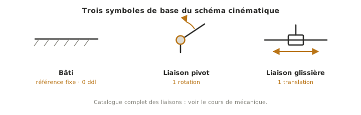
A kinematic diagram links parts (the lines) through standardised joints, each allowing a specific number of motions:
- the revolute joint (liaison pivot) allows one rotation (1 DOF) — the typical articulation of an arm;
- the prismatic joint (liaison glissière) allows one translation (1 DOF) — a carriage on a rail;
- the fixed joint (encastrement) allows no motion at all (0 DOF);
- the frame (bâti), drawn hatched, is the reference part taken as fixed.
You read the chain from the frame out to the end, adding up the degrees of freedom. The symbols are standardised: they do not depend on how the real part is drawn, which is what makes the diagram readable by any mechanical engineer. The full catalogue of joints (spherical, cylindrical, planar and so on) and the formal method of mobility calculation belong to the mechanics course. This page gives you the reading, not the formalism.
Example — The 3-axis arm
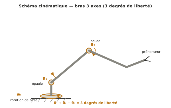
The arm used as the running example comes down to three revolute joints in series: a base rotation (vertical axis), then two articulations (shoulder, elbow). Each joint adds one degree of freedom → 3 DOF, just what it takes to bring the gripper to a position within its working volume. The diagram reads at a glance: you see the architecture (serial), you count the axes (so the motors to plan for) and you locate the joints to be sized, without having drawn a single part yet.
See also
- Functional block diagram — describes the functions and their flows, a view complementary to that of the motions
- Energy chain — the chain that sets the mechanism moving (motors, transmissions)
- Concept — the phase where the mechanical architecture is frozen
- Mechanics course (colleagues) — catalogue of joints, kinematic screws, mobility calculation